Warning
OhmPi is a participative project open to all, it requires skills in electronics and to respect the safety rules. OhmPi must be assembled in a professional context and by people competent in electronics. The OhmPi team cannot be held responsible for any material or human damage which would be associated with the use or the assembly of OHMPI. The OhmPi team cannot be held responsible if the equipment does not work after assembly.
Assembling the 64-electrode OhmPi
1 Measurement board v2024 + 4 MUX board v2023 + 1 Digital power supply (DPH5005)
TODO :list on tools and components
1 |
|
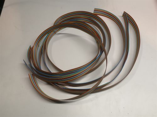
Cut 4 ribbon cables composed of 16 wires each to the proper length (about 1.5m). Each wire corresponds to an electrode. |
2 |
|
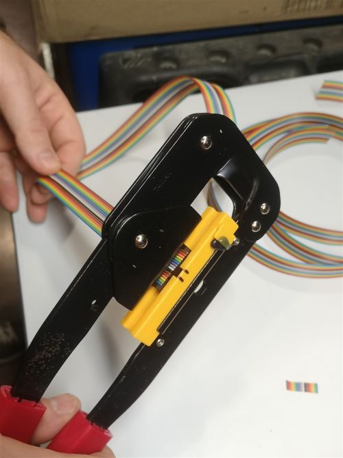
Crimp the ribbon cable on the corresponding idc connector with a suitable clamp. Pay attention to the direction ofthe cables. Unbalanced IDC connector. The ribbon cable must be perpendicular to the connector. |
3 |
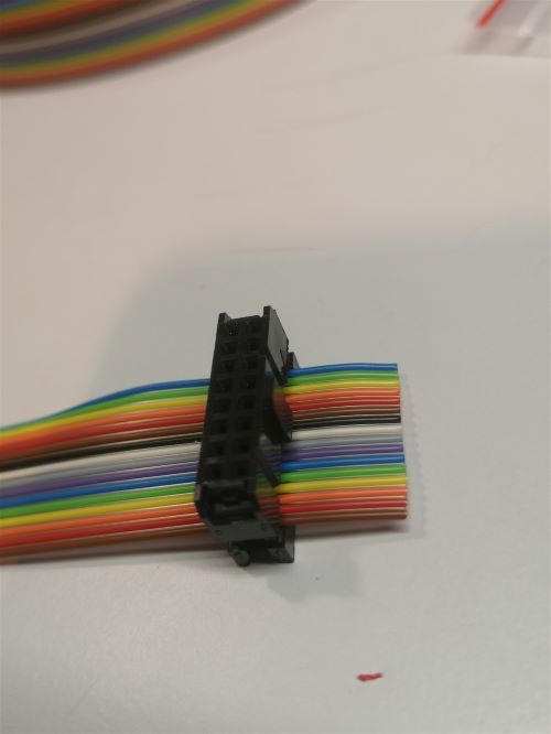
|
Example of IDC connector mounting. The wires should run as perpendicular as possible to the IDC connector. |
Warning
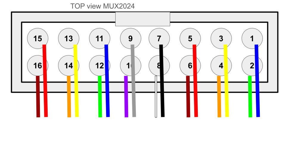
In MUX2024, the wiring of the electrodes from the IDC connector follows the order below (different from MUX2023). Take this into account if you wire your ribbon cable to further connectors or screw terminals.
4 |
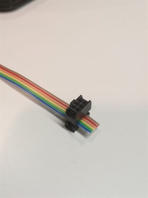
|
Same for a 6 wires ribbon cable of 1 m length. |
5 |
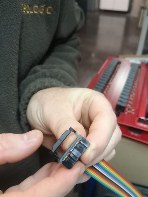
|
Cut the ribbon cable flush with the IDC connector. |
6 |
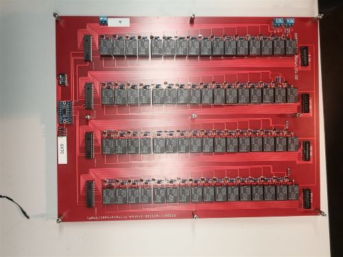
|
Position 9 spacers above the MUX board, and 9 spacers below |
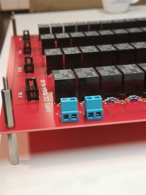
|
|
Profile view for mounting the spacers above and below. |
7 |
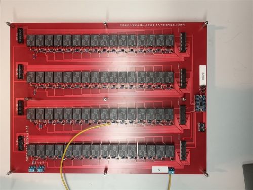
|
Cut a 50 cm long wire of any color (here yellow). Strip and tin each end of the wire. Install the wire “A” on the screw terminal of MUX board « A » |
8 |
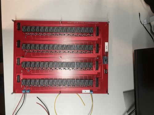
|
Cut a red wire and a black wire of 50 cm length. Strip, tin and place the wires on the left screw terminal as shown in the picture: i)Red wire 12 V, ii) Black wire GND |
9 |
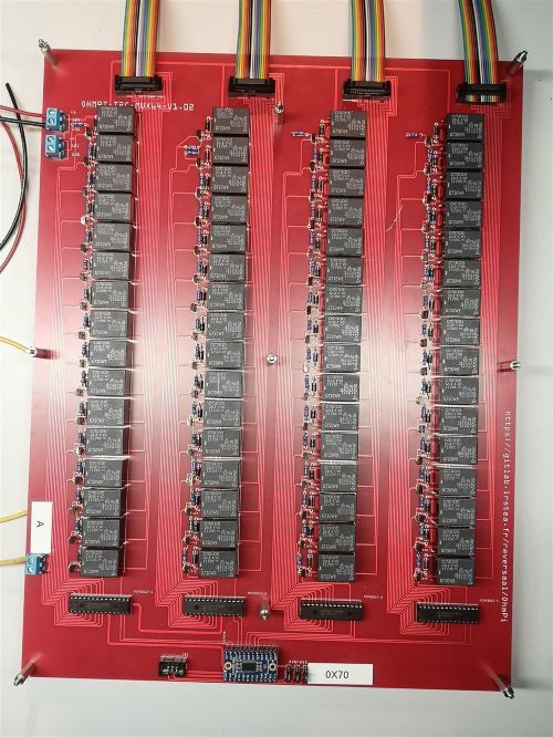
|
Mount the 4 ribbon cables (16-wires each) with IDC connectors. A small noise is often heard when the IDC connector is clipped in place. |
10 |
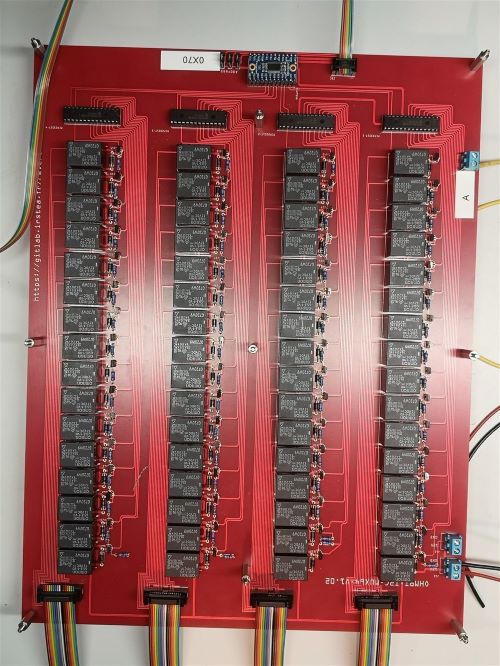
|
Mount the ribbon cables with 6-wires with the corresponding IDC connectors |
11 |
|
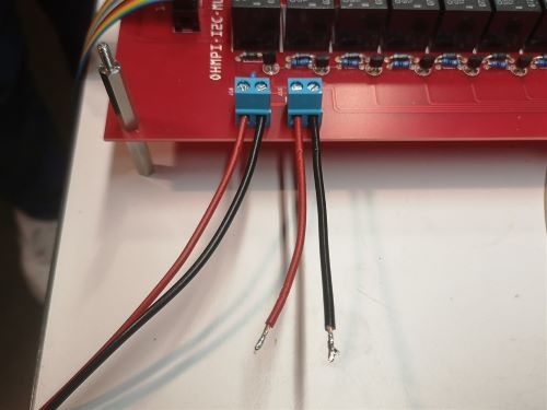
Cut a red wire and a black wire of 10 cm length. Strip and tin the wires at the ends. Mount the red wire on the 12V input and the black wire on the GND input on the right screw terminal. |
12 |
|
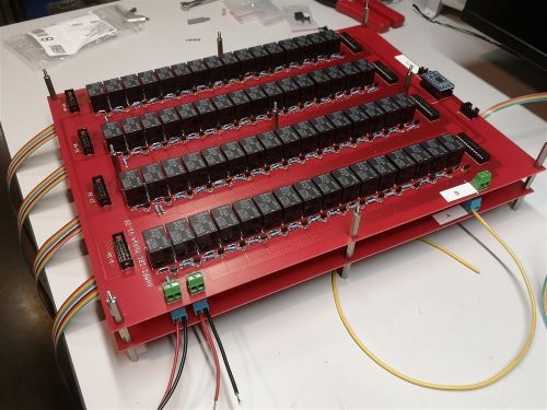
Mount and fix the second MUX board “B” on the first with the help of 9 spacers. |
13 |
|
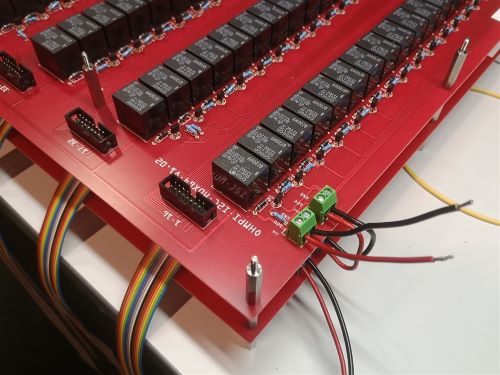
Cut, strip and tin a red wire and a black wire of 10 cm length. Mount the wires on the left screw terminal. Red wire 12V input, black wire GND input. Connect the red and black wires from board A to the right screw terminal of board B. Red wire 12V input. Black wire GND input. |
14 |
|
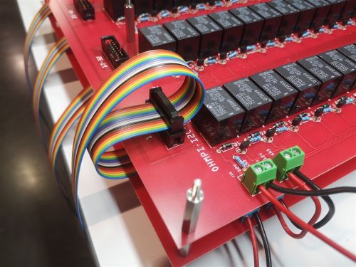
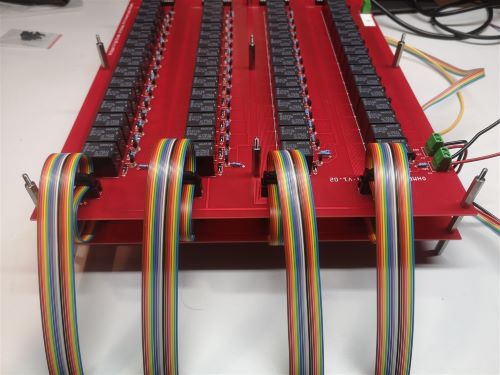
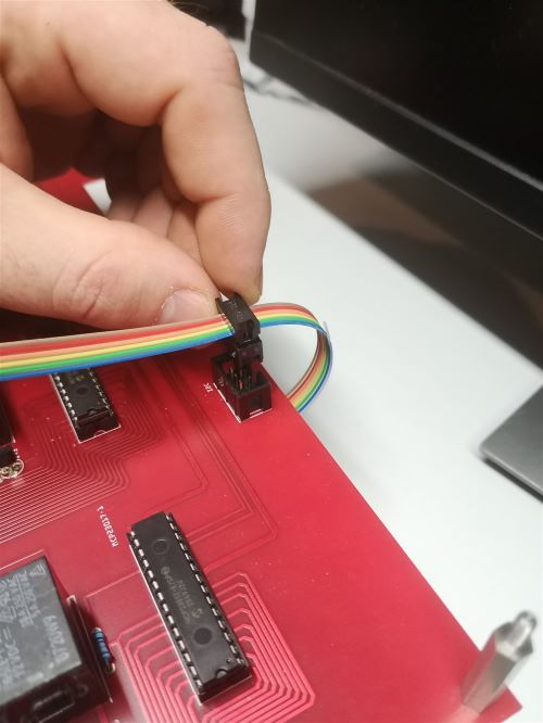
Crimp a 16 wires IDC connector on the ribbon cable at about 15 cm from the previous connector. Please, pay attention to the direction of the cable before the crimp procedure. Mount the ribbon cable on the IDC connector on the board. |
15 |
|
Repeat the operation for the other 3 ribbon cables. |
16 |
|
Repeat the operation for the 6 wires ribbon cable. |
17 |
|
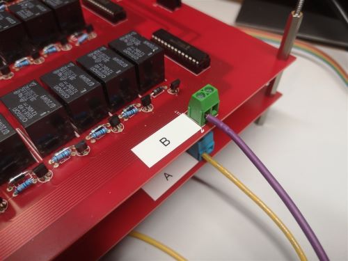
Cut a 50 cm long wire “here purple” (Color not relevant but to be defined). Strip and tin the wire at its ends. Position the wire on the input B of the screw terminal of the multiplexing board B. |
18 |
|
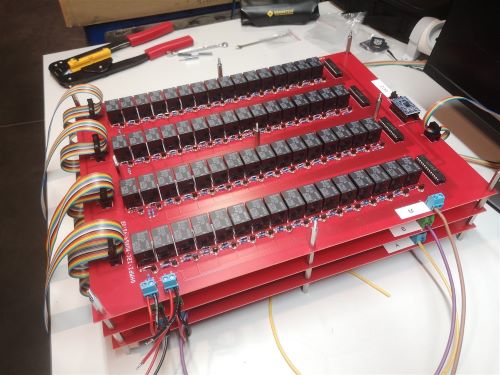
Repeat all these operations for the third MUX board called “M”. |
19 |
|
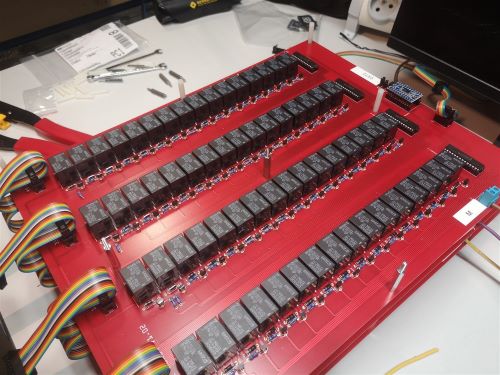
Repeat the operations for the fourth MUX Boards. Attention, it is necessary to position 5 different spacers (here nylon screw hex spacers) in between the “M” board and the “N” MUX Board (as shown on the photograph). Refer to the following photographs for more details on the assembly of the spacers |
20 |
|
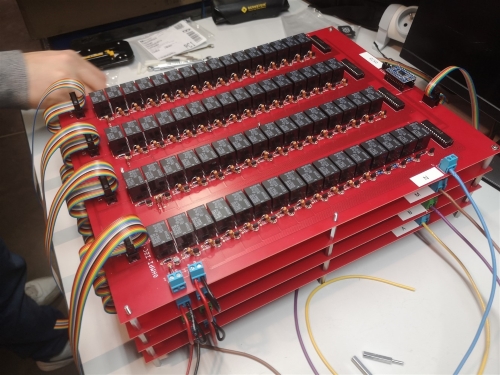
When mounting the 4th MUX board (“N”), screws can be placed on the nylon spacers to fix the boards together. Note that the other spacers could be used for this purpose. Connect ribbon cables (16 wires) from board 3 to board 4 as previously described. Connect the red wire (12V) of MUX board “M” to the 12V terminal of the right screw terminal of MUX Board “N”. Connect the black wire (GND) of MUX board “M” to the GND screw terminal on MUX board “N”. |
21 |
|
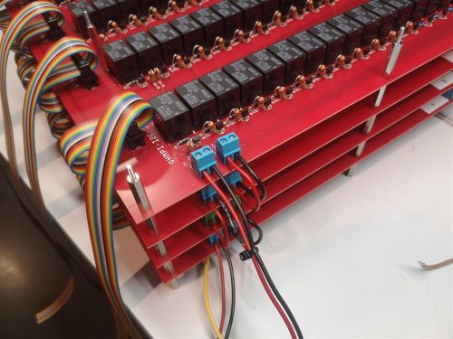
Cut a red wire and a black wire of one meter length. Place the red wire on terminal “12V” and the black wire on terminal “GND” of the left screw terminal. Tie the wires together. |
22 |
|
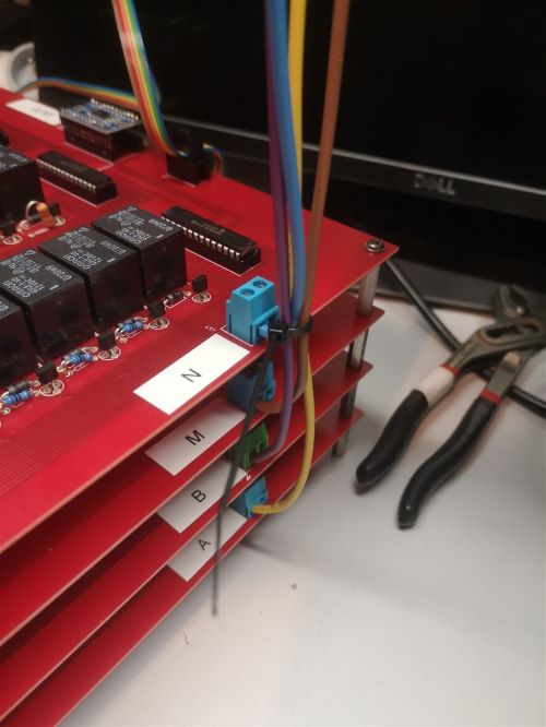
Tie the A, B, M and N wires together |
23 |

|
Cut a PVC/wood plate with the following minimum dimensions : 410 mm * 280 mm * 4 mm, and drill hole (M 3.5 mm) |
24 |

|
Fix the PVC plate |
25 |

|
Drill holes for fixing Raspberry Pi and measurement board |
26 |

|
Install spacer for Raspberry Pi on the pvc plate |
27 |

|
Install spacer for measurement board on the pvc plate |
28 |

|
Fit 9 flat washers and nuts (M3) |
29 |

|
Install Raspberry Pi |
30 |

|
Fit 4 spacers (female/female, M3, 11 mm) |
31 |

|
Install the measurement board on the Raspberry Pi,
|
32 |

|
Fit 3 flat washers and nuts (M3) for measurement board. |
33 |

|
Connect 12V and GND cable from Mux to Measurement board |
34 |

|
The choice is yours: position or fix the DPH5005. connect USB cable between DPH5005 and Raspberry Pi |
35 |

|
Prepare two wires ( 30 cm, 1.5 mm², black and red), and and install two banana plugs |
36 |

|
This is optional, but you could install a switch on the cable connecting to the 12V RX battery. |
37 |

|
Prepare two wires ( ~15 cm, 1.5 mm², black and red), and and install two banana plugs and connect the measurement board and the input of DPH5005 (on the back side) |
38 |

|
Prepare two wires ( ~20 cm, 1.5 mm², black and red), and and install two banana plugs and connect the measurement board (DPS+ and GND) and the output of DPH5005 (front side) |
39 |

|
slide ribbon cable between MUX N and PCV plate, and connect ribbon cable to IDC connector |
40 |

|
Do not connect the MUX electrode cables to the measurement board. |
|
40 |

|
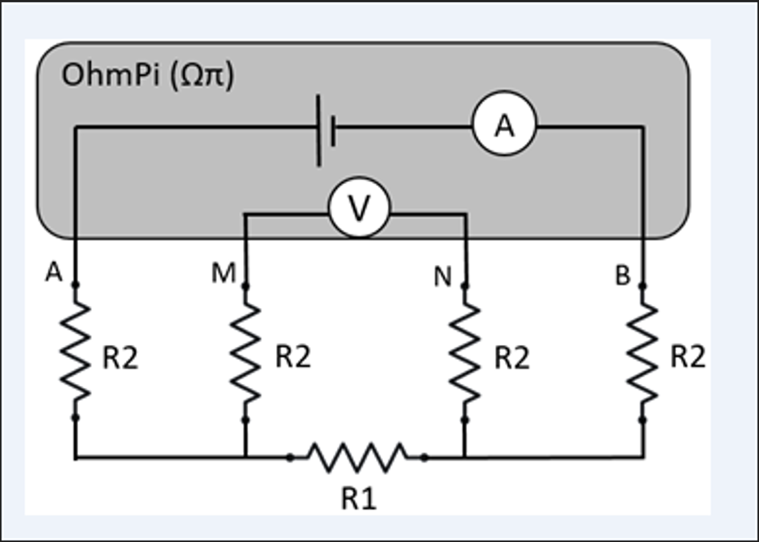
Connect a equivalent circuit R2=1kOhm R1=100 ohm |
Warning
At this point in the build, we consider that you have followed the instructions in Software installation section
Please connect both 12 V Battery for RX and TX.
For direct use of Raspberry Pi Connect Screen, mouse and keybord, for remote control use SSH or VNC.
Now it is possible to carry out the first test on a reference circuit.
Write de following python script your OhmPi folder
import os
import numpy as np
import time
import matplotlib.pyplot as plt
os.chdir("/home/pi/OhmPi")
from ohmpi.ohmpi import OhmPi
k = OhmPi()
41 |
|
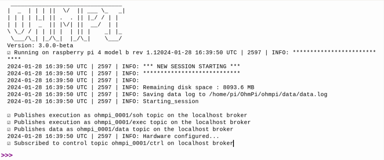
If everything is ok, you get the message upper, if not check all cable, and battery or refer to troubleshooting |
k.test_mux()
You should hear each of the 256 MUX board relays activate and deactivate 1 at a time.
k.run_measurement(quad=[1,4,2,3], tx_volt = 5., strategy = 'constant', dutycycle=0.5)
A measurement will start, and you should obtain your first measurement, with a value of R = 100 ohm (R1 on the equivalent circuit).
If not check, your cable connection and batteries
You can now connect the 4 cables of each MUX to the screw terminals of the measurement board identified ABMN.