System Overview
Warning
OhmPi is a participative project open to all, it requires skills in electronics and to respect the safety rules. OhmPi must be assembled in a professional context and by people competent in electronics. The OhmPi team cannot be held responsible for any material or human damage which would be associated with the use or the assembly of OhmPi. The OhmPi team cannot be held responsible if the equipment does not work after assembly. You may redistribute and modify this documentation and make products using it under the terms of the CERN-OHL-P v2. This documentation is distributed WITHOUT ANY EXPRESS OR IMPLIED WARRANTY, INCLUDING OF MERCHANTABILITY, SATISFACTORY QUALITY AND FITNESS FOR A PARTICULAR PURPOSE. Please see the CERN-OHL-P v2 for applicable conditions.
What is OhmPi?
The OhmPi project was initiated to develop an open-source, open-hardware resistivity meter, particularly designed for the research community, education, and humanitarian or not-for-profit organisations. In the last decade, geoelectrical monitoring has become a popular tool to study and monitor physical processes in hydrology. As novel applications emerge, the need for more accessible and flexible acquisition systems grows in the research community. The flexibility and adaptability of OhmPi makes it particularly suited to develop novel acquisition strategies or design innovative small-scale monitoring experiments.
Note
Anyone who wants to get involved is welcome to join the OhmPi project!
How does it work?
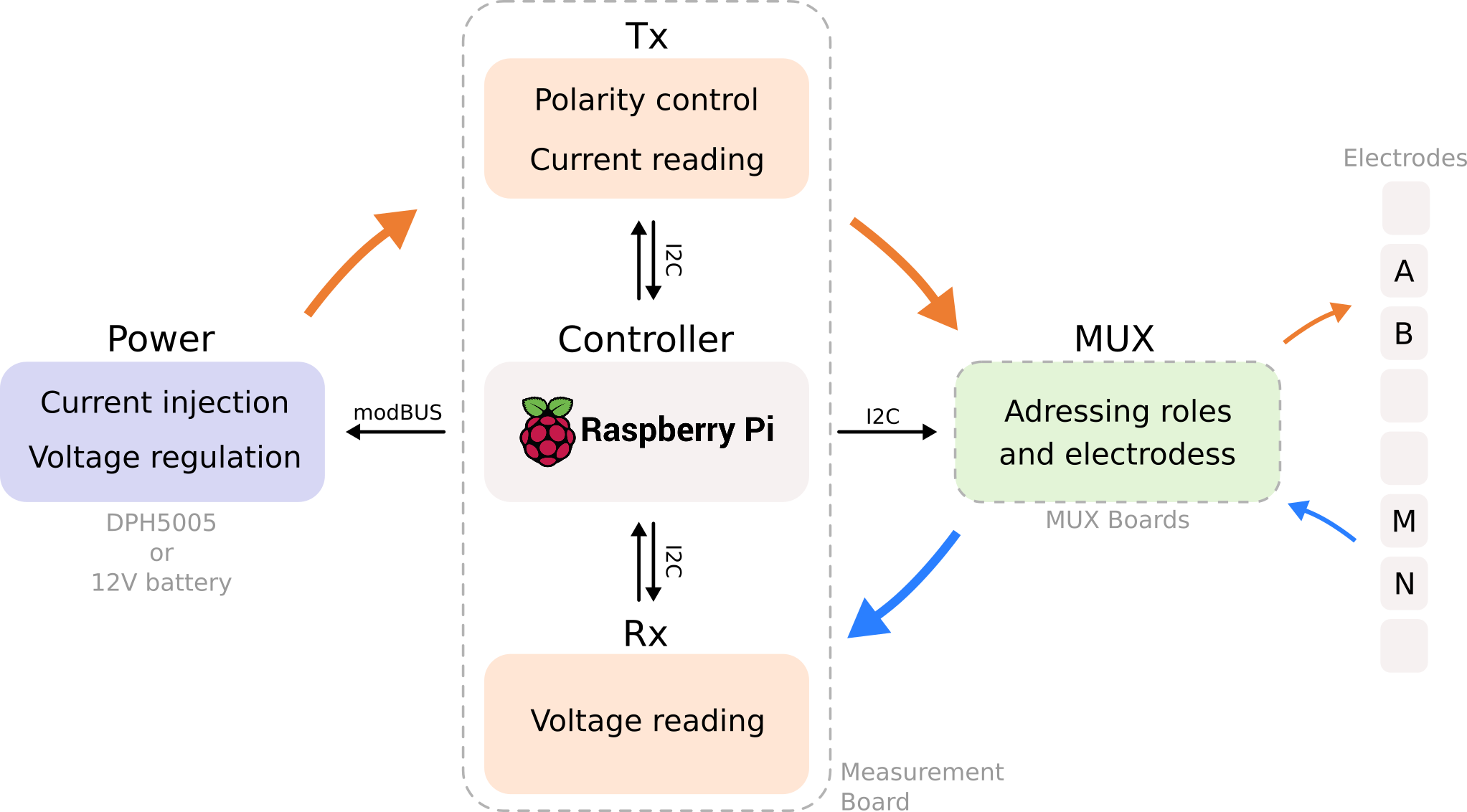
The OhmPi is composed of different modules:
a measurements board (
mb): that measures the current and voltage and modulates the injected current0, 1, … or n multiplexer boards (
mux): that address different electrodesa power supply (
pwr): either a 12V battery or a more advanced power supply where we can control the voltage/currenta general controller (
ctrl): to control the measurement board, multiplexer boards and power supply (=raspberrypi)
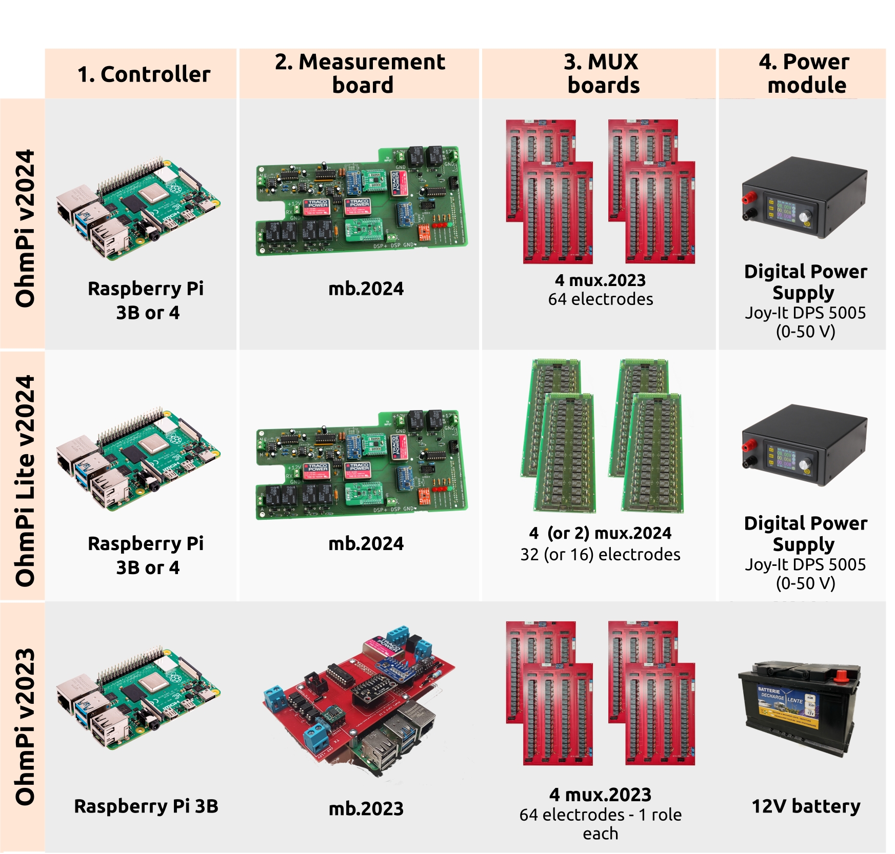
These modules exist in different versions and can be combined using a configuration file. You can then upgrade your measurement board or power supply for specific applications.

OhmPi hardware flowchart.
In “BUILD OHMPI BOARDS” section we detail how to build each single module of an OHMPI system.
How does it look like?
Warning
We strongly recommend to test the assembled system in a controlled environment (in the lab, on resistor boards) before deploying in the field!

Recommended configurations
Applications |
Measurement Board |
Mux |
Raspberry Pi |
Power supply |
Config file name |
64 or more electrodes
for field monitoring
|
mb v2024 |
Mux v2023 |
Raspberry Pi 3 Model B
or 4 model B
|
DPH5005 |
config_mb_2024_0_2__4_mux_2023_dph5005.py |
8, 16, 32, 48 electrodes
for field monitoring
|
mb v2024 |
Mux v2024 |
Raspberry Pi 3 Model B
or 4 model B
|
DPH5005 |
config_mb_2024_0_2__4_mux_2024_2roles_dph5005.py |
8, 16, 32, 48 electrodes
for laboratory monitoring
|
mb v2024 |
Mux v2024 |
Raspberry Pi 3 Model B
or 4 model B
|
12V Battery |
config_mb_2024_0_2__4_mux_2024_2roles.py |
4 electrodes concrete sample
Laboratory (Rhoa and IP)
|
mb v2024 |
None |
Raspberry Pi 3 Model B |
DPH5005 |
config_mb_2024_0_2_dph5005.py |
4 electrodes soil sample
laboratory (Rhoa and IP)
|
mb v2024 |
None |
Raspberry Pi 3 Model B |
12V Battery |
config_mb_2024_0_2.py. |
4 electrodes-soil sample
laboratory (only Rhoa)
|
mb v2023 |
None |
Raspberry Pi 3 Model B |
12V Battery |
config_mb_2023.py |
Another possible combination is to use MUX v2023 with MUX v2024 together, which allows the addition of a series of 8 electrodes to a 64-electrode system. This could be useful if one is looking to build e.g. a 96 electrode system, which would therefore feature 4 MUX 2023 (64 electrodes) + 4 MUX 2024 (32 electrodes).
In “BUILD OHMPI SYSTEMS” section we detail examples of OHMPI systems assemblies in different versions.
Today, version 1.0x is no longer maintained, but all boards from v2023 upwards are compatible with each other. This is the major innovation of 2024. Depending on your needs and applications, you can choose the board you are going to use.
How to build an OhmPi successfully?
and become an OhmPier!
Here are few tips:
make good soldering: a lot of issues arise from bad soldering or soldering on the wrong side of PCB. Take your time, check your soldering with the multimeter, this will save you a lot of time afterwards.
go step by step: follow the documentation, start by building a measurement board, then build multiplexers, then assemble the system.
hardware check: for each board, check your electronics with the multimeter (there are checklists at the end of the “build your board” section)
software test: use the software tests once the system is assembled. Always check with a resistor board before going on the field.
if needed, seek help: consult the troubleshooting section or ask help on Discord. Look at the open or closed gitlab issues.
provide feedback and share your experience: OhmPi is an open-source open-hardware project, if you found a bug or have an idea to improve the hardware or the code, please use the GitLab repository and raise issues. You can also share your experience with the community.
Where are the OhmPi?
If you want your system to appear on the map, register your OhmPi.
