Warning
OhmPi is a participative project open to all, it requires skills in electronics and to respect the safety rules. OhmPi must be assembled in a professional context and by people competent in electronics. The OhmPi team cannot be held responsible for any material or human damage which would be associated with the use or the assembly of OHMPI. The OhmPi team cannot be held responsible if the equipment does not work after assembly.
Measurement board v2024
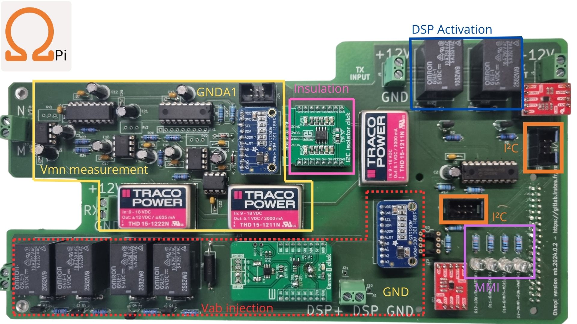
The 2024.0.2 measurement board has been developed to replace the 2023.0.1 measurement board. It offers superior performance compared to its predecessor. The current measurement component has not evolved and presents no major differences. However, the major upgrade is the Mikroe-2C Isolator Click module (’https://www.mikroe.com/i2c-isolator-click’) . Specifically, it provides electrical isolation for the Vmn measurement set. This isolation allows for injection voltages (Vab) up to 200V
Assemble
Schematics
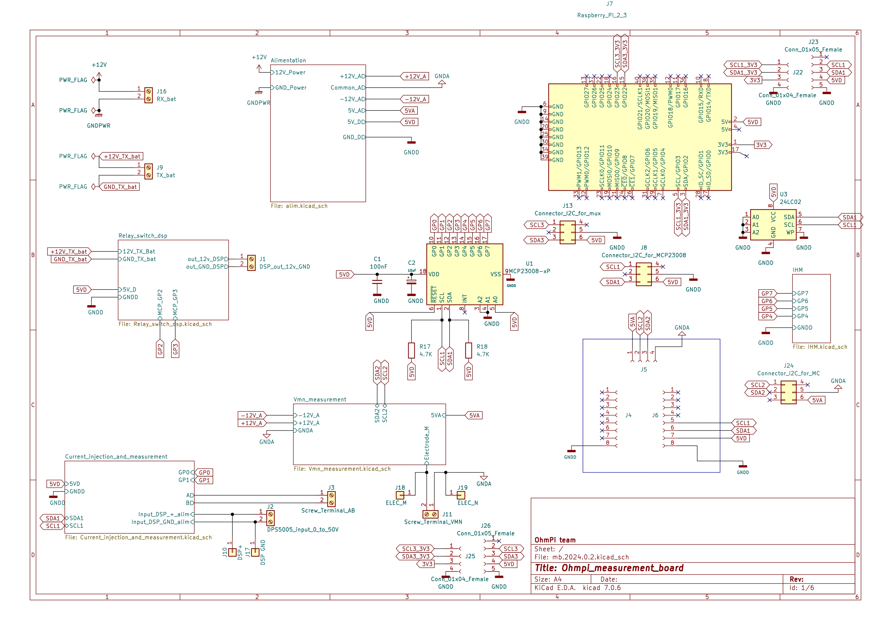
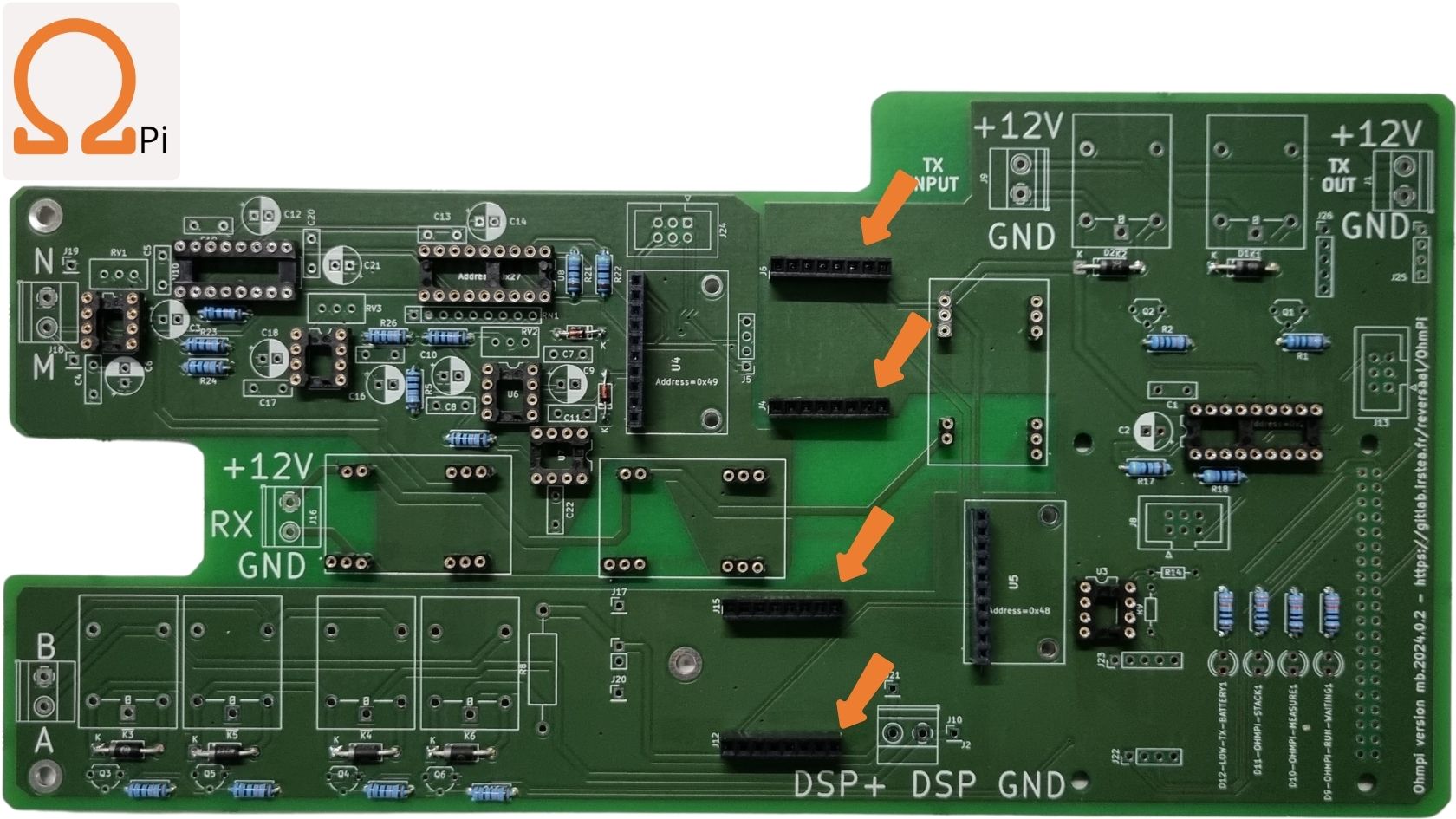
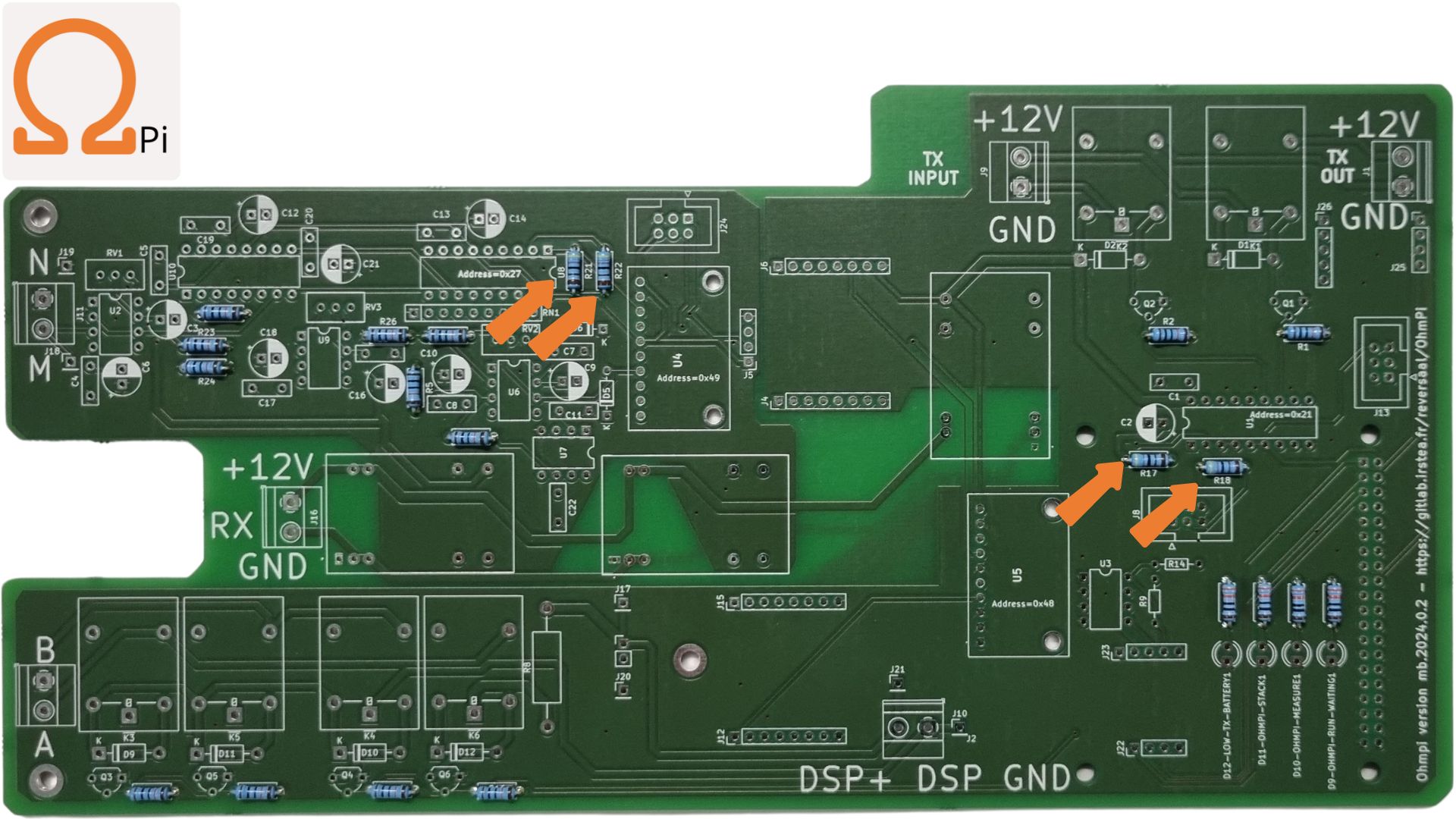
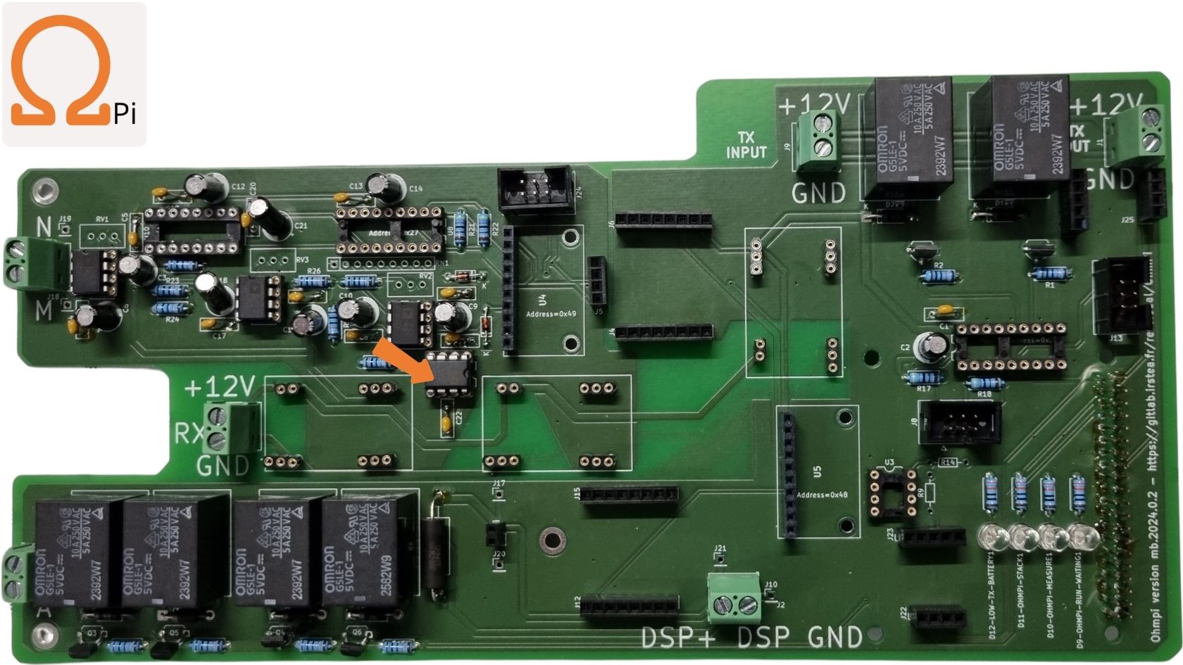
Overview of the measurement board.
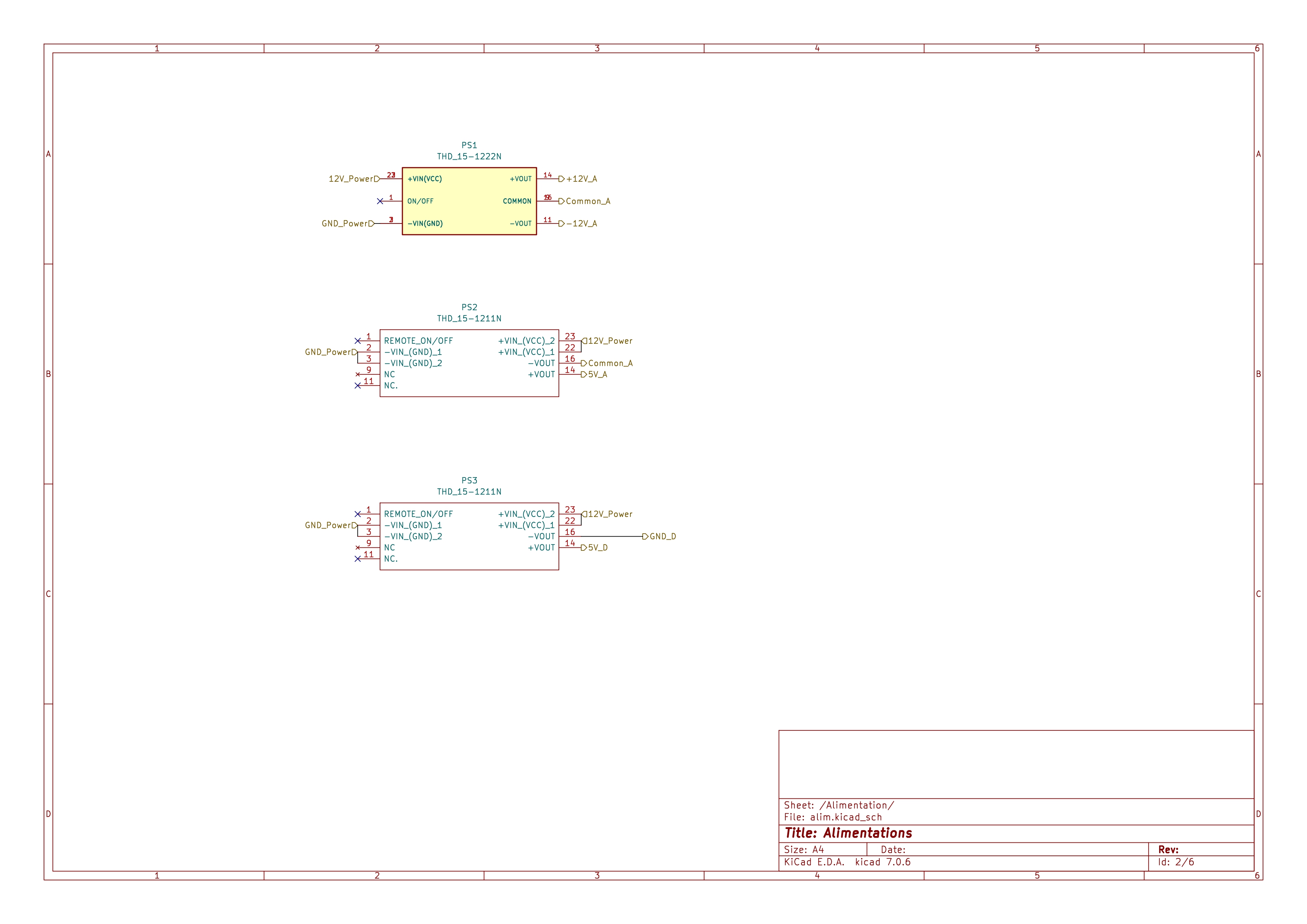
Schematic of the power supply.
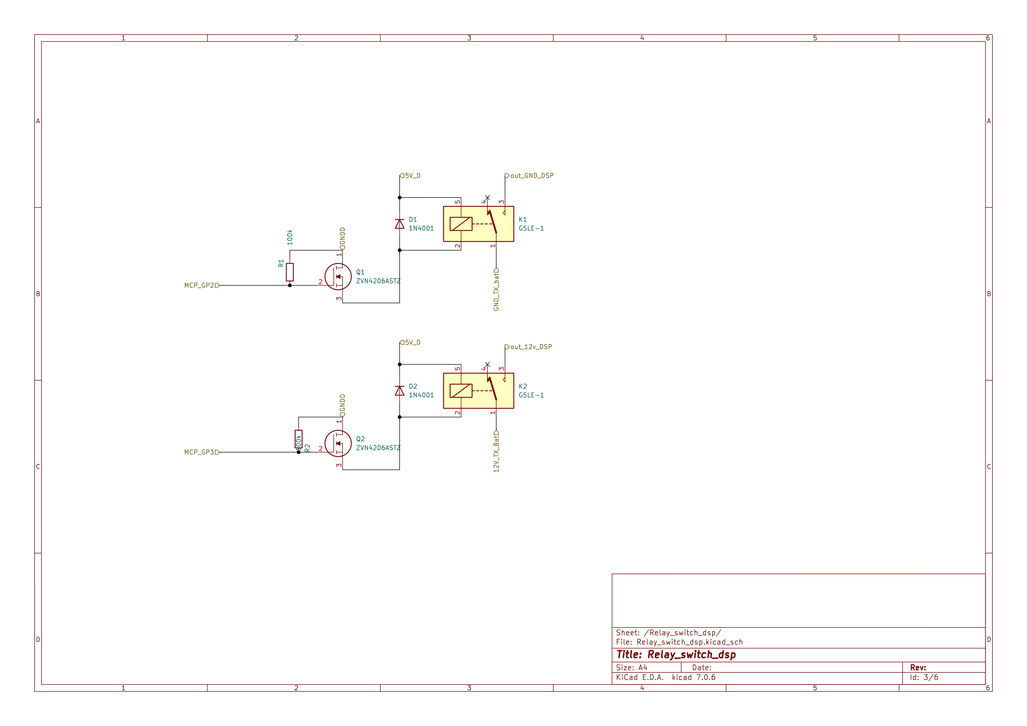
Schematic of the DPS (digital power source) power supply (e.g. DPH5005).
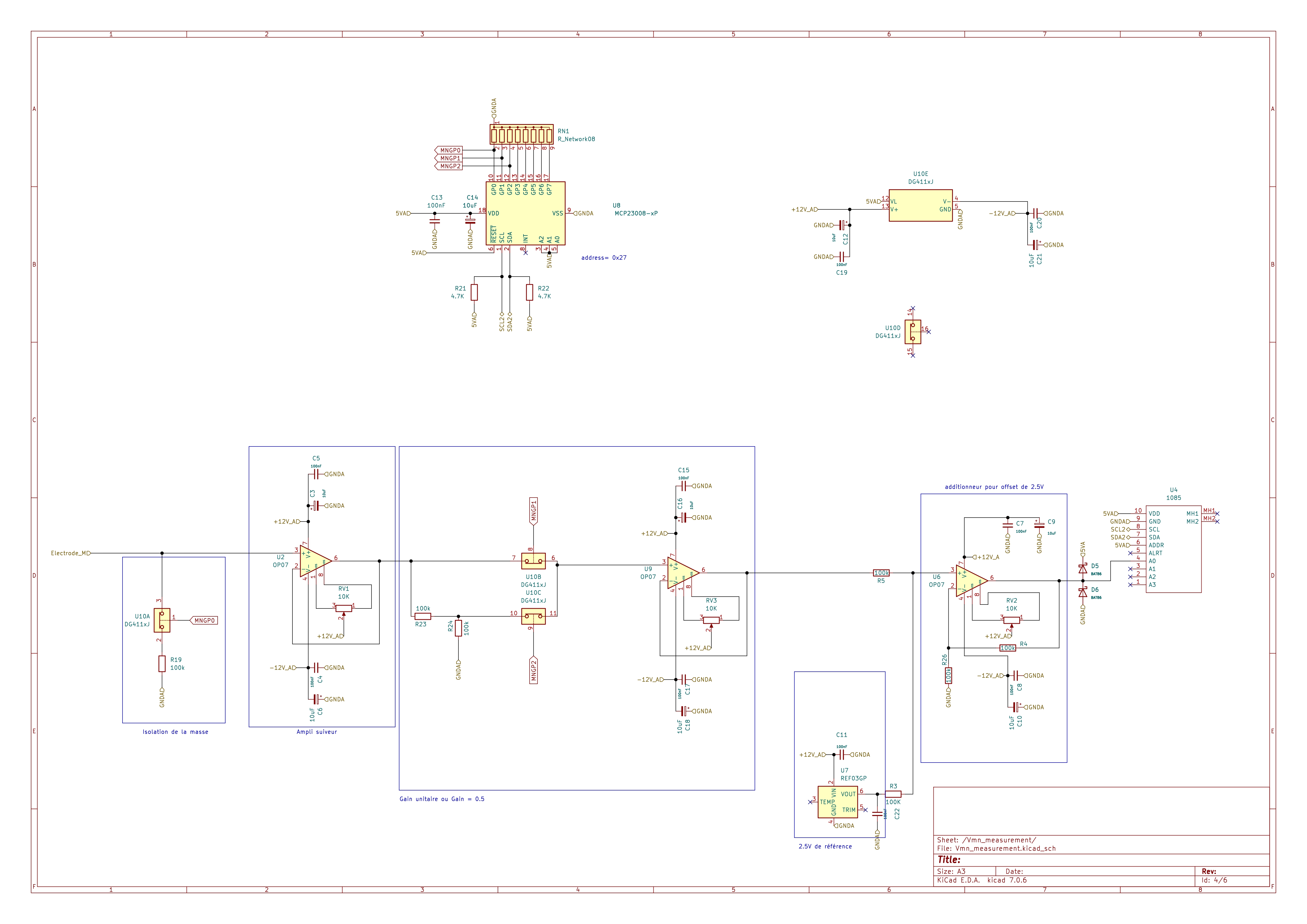
Schematic of the Vmn signal conditioning.
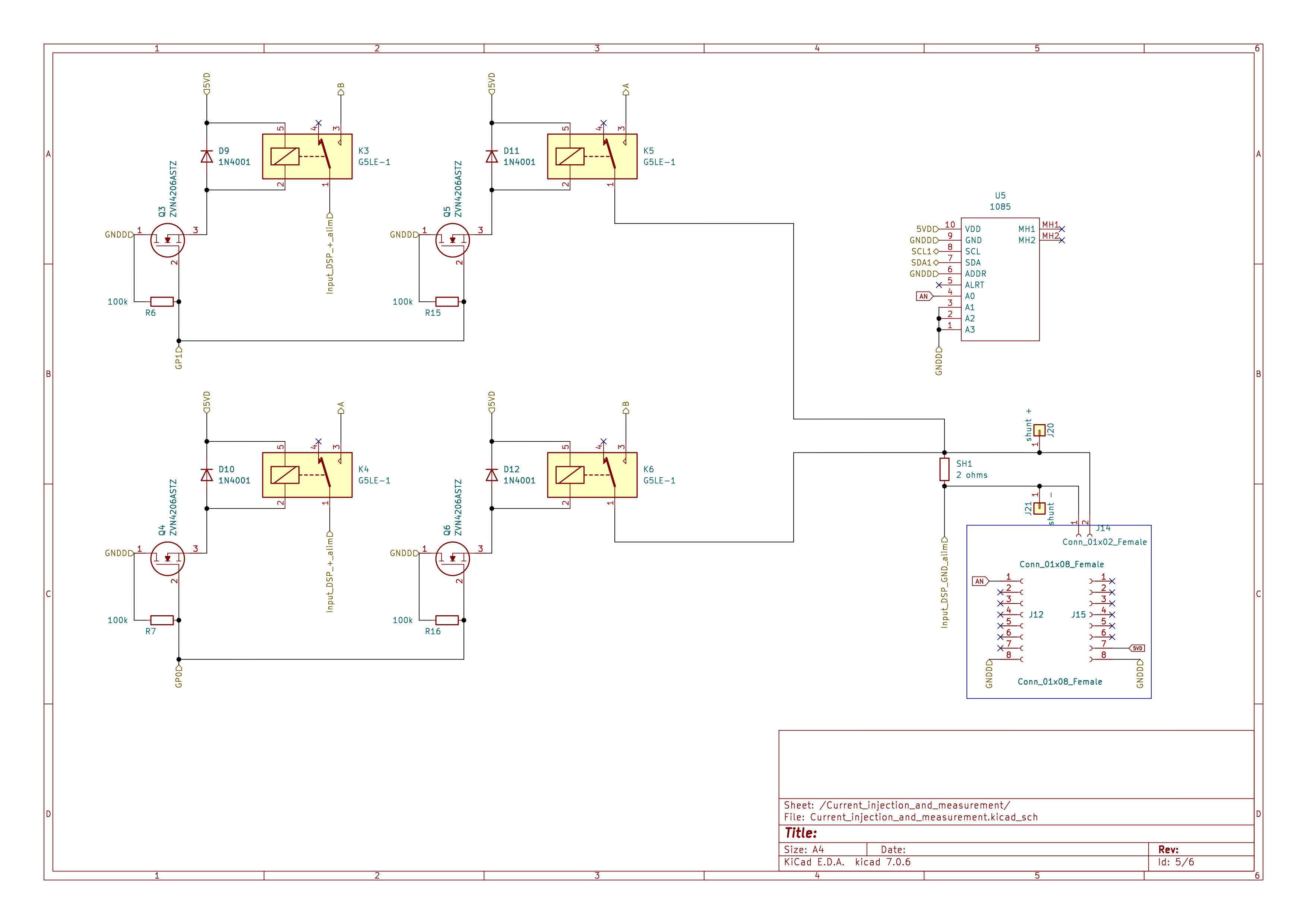
Schematic of the current injection and measurement.

Schematic of the human-machine interface.
Required components
Component |
Quantity |
Cost per unit |
Reference |
Order platform |
Manufacturer |
Manufacturer reference |
Description |
Web link |
Total cost EUR excl.VAT |
|---|---|---|---|---|---|---|---|---|---|
100 kOhm resistor |
14 |
0.22 |
594-5063JD100K0FT |
mouser |
MBA02040C1003FRP00 |
Vishay |
Metal Film Resistors - Through Hole .4watt 100Kohms 1% 1/8watt body size |
2.90 |
|
1 kOhm resistor 5% |
2 |
0.19 |
603-FMP100JR-52-1K |
mouser |
YAGEO |
https://www.mouser.fr/ProductDetail/YAGEO/FMP100JR-52-1K?qs=PG6CdkgpaC4rfLZElyVcnA%3D%3D |
0.37 |
||
330 Ohms resistor |
3 |
0.31 |
603-MFR-25FRF52-330R |
mouser |
CFR100J330R |
TE Connectivity |
Carbon Film Resistors - Through Hole 330Ohm 1W 500PPM |
1.23 |
|
4.7 kOhms resistor |
2 |
0.31 |
594-NFR25H0004701JR5 |
mouser |
CFR-25JB-52-4K7 |
YAGEO |
Carbon Film Resistors - Through Hole 1/4W 4.7K Ohm 5% |
https://eu.mouser.com/ProductDetail/YAGEO/CFR-25JB-52-4K7?qs=oypCK0zG3252T%2FvSUvCH9g%3D%3D |
1.23 |
2 ohms shunt resistor |
1 |
1.33 |
71-CPF2-F-2/R |
mouser |
WNC2R0FET |
Ohmite |
Wirewound Resistors - Through Hole 2W 2 ohms 1% |
https://eu.mouser.com/ProductDetail/Ohmite/WNC2R0FET?qs=CDPnWzNfzJb5BMolBZTI%252Bw%3D%3D |
1.33 |
50V 1A general purpose rectifier diode DO-41 |
7 |
0.21 |
621-1N4007 |
mouser |
1N4001 |
Diotec |
Semiconductor Rectifiers Diode DO-41 50V 1A |
https://eu.mouser.com/ProductDetail/Diotec-Semiconductor/1N4001?qs=OlC7AqGiEDlll8NA510wmA%3D%3D |
1.28 |
cree LED |
3 |
0.28 |
941-C503BGANCD0E0781 |
mouser |
C503B-GAN-CD0E0781 |
Cree LED |
Standard LEDs - Through Hole Green LED 527nm 5-mmRound 32900-64600mcd |
1.12 |
|
50V 0.2 A small signal schottky diode DO-35 |
2 |
0.44 |
771-BAT86133 |
mouser |
BAT86 113 |
Nexperia |
Schottky Diodes & Rectifiers BAT86/SOD68/DO-34 |
https://eu.mouser.com/ProductDetail/Nexperia/BAT86113?qs=me8TqzrmIYX1ahcmZsx1tg%3D%3D |
0.87 |
OP27E (single ultra offset 8DIP) |
3 |
9.53 |
584-OP27EPZ |
mouser |
OP27EPZ |
Analog Devices Inc. |
Precision Amplifiers LOW-NOISE PRECISION OP AMP |
https://eu.mouser.com/ProductDetail/Analog-Devices/OP27EPZ?qs=WIvQP4zGangDp3uWiH2URA%3D%3D |
28.59 |
MCP23008 (GPIO expander) |
2 |
1.89 |
579-MCP23008-E/P |
mouser |
593 |
Adafruit |
Adafruit Accessories MCP23008 - i2c 8 input/output port expander |
https://eu.mouser.com/ProductDetail/Adafruit/593?qs=GURawfaeGuAf08zux7w%2FuQ%3D%3D |
3.78 |
ADS1115 adafruit board (pack of 3) |
2 |
14.90 |
AZ delivery |
1085 |
Adafruit |
Data Conversion IC Development Tools ADS1115 16-Bit ADC - 4 Channel with Programmable Gain Amplifier |
https://www.az-delivery.de/fr/products/analog-digitalwandler-ads1115-mit-i2c-interface |
14.99 |
|
2.5V precision voltage reference |
1 |
6.12 |
584-REF03GPZ |
mouser |
REF03GPZ |
Analog Devices Inc. |
Voltage References PRECISION LOW-COST 2.5V R |
https://eu.mouser.com/ProductDetail/Analog-Devices/REF03GPZ?qs=WIvQP4zGangjpDFoUwu1Bw%3D%3D |
6.12 |
DG411DJ analog switch |
1 |
2.23 |
781-DG411DJ-E3 |
mouser |
DG411DJ-E3 |
Vishay |
Analog Switch ICs HIGH SPEED DG411 DIP-16 |
2.23 |
|
unpolar capacitor 100nF |
12 |
0.21 |
594-K104K15X7RF5UL2 |
mouser |
K104K15X7RF5UL2 |
Vishay |
Multilayer Ceramic Capacitors MLCC - Leaded K 50V 100NF +/- 10 % X7R AMMO E3 |
2.57 |
|
polarized capacitor 10uF |
10 |
0.27 |
598-SEK100M063ST |
mouser |
EEU-EB1J100S |
Panasonic |
Aluminum Electrolytic Capacitors - Radial Leaded 10uF 63volts AEC-Q200 |
https://eu.mouser.com/ProductDetail/Panasonic/EEU-EB1J100S?qs=cEAFgkeRviBcbEMSGHCq5g%3D%3D |
2.70 |
N channel 60V 600mA 700mW through hole transistor (ZVN4206ASTZ) |
7 |
0.34 |
522-ZVN4306AV |
mouser |
ZVN4206ASTZ |
Diodes Incorporated |
MOSFET N-Chnl 60V |
https://www.mouser.be/ProductDetail/onsemi-Fairchild/2N7000BU?qs=k2x4EL1%2FKj6oeXMHAfSm5A%3D%3D |
2.01 |
THD1512 11N (output 5V) |
2 |
48.53 |
495-THD15-1211N |
mouser |
THD 15-1211N |
TRACO Power |
Isolated DC/DC Converters - Through Hole Product Type: DC/DC, Package Style: DIP-24, Output Power (W): 15, Input Voltage: 9-18 VDC, Output 1 (Vdc): 5.1, Output 2 (Vdc): N/A, Output 3 (Vdc): N/A |
https://eu.mouser.com/ProductDetail/TRACO-Power/THD-15-1211N?qs=ckJk83FOD0X2IyoEoPcnmg%3D%3D |
97.06 |
THD1512 22N (output 12V) |
1 |
52.00 |
495-THD-15-1222N |
mouser |
THD 15-1222N |
TRACO Power |
Isolated DC/DC Converters - Through Hole Product Type: DC/DC, Package Style: DIP-24, Output Power (W): 15, Input Voltage: 9-18 VDC, Output 1 (Vdc): 12, Output 2 (Vdc): -12, Output 3 (Vdc): N/A |
https://www.mouser.be/ProductDetail/TRACO-Power/THD-15-1222N?qs=ckJk83FOD0UVycxQxcHQFw%3D%3D |
52.00 |
terminal block 12V (3 pôles) - optional |
1 |
1.98 |
651-1751251 |
mouser |
https://www.mouser.fr/ProductDetail/Phoenix-Contact/1751251?qs=wdlOgCqRo4w4Go2awGHrzA%3D%3D |
1.98 |
|||
terminal block 12V (2 pôles) |
6 |
0.85 |
649-VI02215200J0G |
mouser |
VI0221520000G |
Amphenol |
Fixed Terminal Blocks TB RIS CLA 180 STACK |
https://eu.mouser.com/ProductDetail/Amphenol-Anytek/VI0221520000G?qs=Mv7BduZupUi3lmtBYXCXvw%3D%3D |
5.09 |
mikroe i2C isolator |
1 |
16.74 |
932-MIKROE-1878 |
mouser |
MIKROE-1878 |
Mikroe |
Interface Development Tools I2C Isolator click |
https://eu.mouser.com/ProductDetail/Mikroe/MIKROE-1878?qs=k5OWtXsTJao5L2rHk53Deg%3D%3D |
16.74 |
mikroe shunt current sensor |
1 |
24.18 |
2475770 |
RS |
MIKROE-4976 |
Mikroe |
Power Management IC Development Tools Current 7 Click |
24.18 |
|
SparkFun Accessories Level Translator Breakout |
2 |
4.03 |
474-bob-15439 |
mouser |
BOB-15439 |
SparkFun Electronics |
SparkFun Accessories Level Translator Breakout - PCA9306 |
https://eu.mouser.com/ProductDetail/SparkFun/BOB-15439?qs=P1JMDcb91o4XoNPr%252B0Xi4g%3D%3D |
8.06 |
omhron G5LE relay |
7 |
1.44 |
653-G5LE-1-DC5 |
mouser |
G5LE-1A4-DC5 |
Omron |
General Purpose Relays Power PCB Relay SPST-NO Sealed 5VDC |
https://eu.mouser.com/ProductDetail/Omron-Electronics/G5LE-1A4-DC5?qs=pWf36BUtxBgFTk6ytLB7NQ%3D%3D |
8.64 |
DIP for MCP23008 (18 pins) |
2 |
1.33 |
200-ICA318STT |
mouser |
110-47-318-41-001000 |
Mill-Max |
IC & Component Sockets STANDRD SOLDER TAIL DIP SOCKET |
https://eu.mouser.com/ProductDetail/Mill-Max/110-47-318-41-001000?qs=5aG0NVq1C4xxoOYTdZ6dOw%3D%3D |
2.66 |
DIP for OP27E (8 pins) |
4 |
1.39 |
575-144308 |
mouser |
110-13-308-41-001000 |
Mill-Max |
IC & Component Sockets 8P GLD PIN GLD CONT |
https://eu.mouser.com/ProductDetail/Mill-Max/110-13-308-41-001000?qs=WZeyYeqMOWeYjIS4tXLt7Q%3D%3D |
6.95 |
DIP for DG411DJ (16 pins) |
1 |
1.05 |
855-D2816-42 |
mouser |
110-44-316-41-001000 |
Mill-Max |
IC & Component Sockets 16P TIN PIN TIN CONT |
1.05 |
|
header for raspberrypi |
1 |
1.87 |
474-PRT-16764 |
mouser |
PRT-14017 |
SparkFun Electronics |
Raspberry Pi Accessories Raspberry Pi GPIO Tall Header - 2x20 |
https://eu.mouser.com/ProductDetail/SparkFun/PRT-14017?qs=a4BXICGgSn%2F%252BaML822b65A%3D%3D |
1.87 |
header socket 1 row 5 positions |
2 |
1.97 |
571-5-534237-3 |
mouser |
5-534237-3 |
TE Connectivity |
Headers & Wire Housings REC 1X05P VRT T/H |
https://eu.mouser.com/ProductDetail/TE-Connectivity/5-534237-3?qs=Eln3I3szM1klmLr%252BSZCsuQ%3D%3D |
3.94 |
header socket 1 row 4 positions |
3 |
1.46 |
571-215297-4 |
mouser |
5-534237-2 |
TE Connectivity |
Headers & Wire Housings REC 1X04P VRT T/H |
https://eu.mouser.com/ProductDetail/TE-Connectivity/5-534237-2?qs=GYgf5PdsjzkI3hK2O1eiLQ%3D%3D |
4.38 |
header socket 1 row 8 positions |
4 |
1.74 |
571-215297-8 |
mouser |
5-535541-6 |
TE Connectivity |
Headers & Wire Housings REC 1X08P VRT T/H |
https://eu.mouser.com/ProductDetail/TE-Connectivity/5-535541-6?qs=xDp7PGUNC%252BuqVwKJJvkWQw%3D%3D |
6.96 |
header socket 1 row 10 positions |
3 |
2.71 |
571-5342378 |
mouser |
SSW-110-02-G-S |
Samtec |
Headers & Wire Housings Tiger Buy Socket Strip with PCB Tails, .100” Pitch |
https://eu.mouser.com/ProductDetail/Samtec/SSW-110-02-G-S?qs=rU5fayqh%252BE0w1ORXZiBQpw%3D%3D |
8.13 |
header socket 1 row 2 positions |
1 |
1.02 |
571-215297-2 |
mouser |
SSW-102-02-G-S |
Samtec |
Headers & Wire Housings Tiger Buy Socket Strip with PCB Tails, .100” Pitch |
https://eu.mouser.com/ProductDetail/Samtec/SSW-102-02-G-S?qs=rU5fayqh%252BE2ZEIMTlw%2FBLw%3D%3D |
1.02 |
header pins 1 row 10 positions |
1 |
1.24 |
571-1-826629-0 |
mouser |
1-826629-0 |
TE Connectivity |
Headers & Wire Housings 10P SINGLE ROW |
https://eu.mouser.com/ProductDetail/TE-Connectivity/1-826629-0?qs=FazuUmncXom0aPLI6ZgGxg%3D%3D |
1.24 |
IDC sockets (go on the ribon cable) |
2 |
0.43 |
710-61200623021 |
mouser |
61200623021 |
Wurth Elektronik |
Headers & Wire Housings WR-BHD 2.54mm Female 6P Strt IDC Conn |
https://eu.mouser.com/ProductDetail/Wurth-Elektronik/61200623021?qs=PhR8RmCirEabk1Ywkdxzfw%3D%3D |
0.86 |
IDC pins |
3 |
1.32 |
571-1761681-1 |
mouser |
1761681.0-1 |
TE Connectivity |
Headers & Wire Housings IDC LOW PRO HDR 6P VERT HT BLACK |
https://eu.mouser.com/ProductDetail/TE-Connectivity/1761681-1?qs=BqFpTYCQ3dLAeZ2wzdz7aw%3D%3D |
3.96 |
Raspberryp pi 4 |
1 |
55.80 |
358-SC1111 |
mouser |
Raspberry Pi |
SC1111 |
Raspberry Pi |
https://www.mouser.be/ProductDetail/Raspberry-Pi/SC1111?qs=HoCaDK9Nz5fnLhlMNnKTiQ%3D%3D |
55.80 |
socket to cut for 3 THD |
3 |
1.73 |
575-8014701210012000 |
mouser |
Mil-Max |
801-47-012-10-012000 |
https://www.mouser.be/ProductDetail/Mill-Max/801-47-012-10-012000?qs=5aG0NVq1C4x40xNvDlnKzg%3D%3D |
5.19 |
|
PCB measurement board (pack of 3) |
1 |
Aisler |
70.00 |
||||||
Resitor network 100K |
1 |
652-4309R-1LF-100K |
mouser |
||||||
TOTAL |
461.08 |
||||||||
To order the PCB (on Aisler or other manufacturers), you just need to drag and drop the .kicad_pcb (e.g. PCB_boards/measurement_boards/mb.2024.1.0/mb.2024.1.0.kicad_pcb) file into their web interface. The web interface will load the PCB and walk you through different steps.
Interactive BOM list
Before starting: how to soldering
How to Solder Electronic Components <https://www.sciencebuddies.org/science-fair-projects/references/how-to-solder>
Description
Note
Since measurement board v2024.1.0, a discharge relay has been added next to the current click. This relay is equipped with similar electronics to the other relays of the board (i.e. 100 kOhm resistor, ZVN transistor, Omron relay). It enables to quickly discharge the current of the DPH5005 when switching between Vab voltages. To control this relay, we had to remove one LED (so there are only 3 LEDs). Note that your board will still work even if you do not install the relay. The mounting of the discharge relay is not included in the pictures below but mount it at the same time you mount the other relays.
Soldering various RESISTOR on the measurement board PCB
STEP 1: Soldering thirteen 100 kOhm resistors.

STEP 2: soldering four (or three) 330 ohm resistors.
STEP 3: Soldering four (or two) 4K7 ohm resistors.
Soldering DIODE on the measurement board PCB
STEP 4: Soldering six diodes 1N4007.
Soldering SCHOTTKY DIODE on the measurement board PCB
STEP 5: Soldering two Schottky diodes bat85 or bat86.
STEP 6: Soldering five DIP-8 sockets. Pay attention to the direction of the notch.
STEP 7: Soldering two DIP-18 sockets.
STEP 8: Soldering one DIP-16 socket.
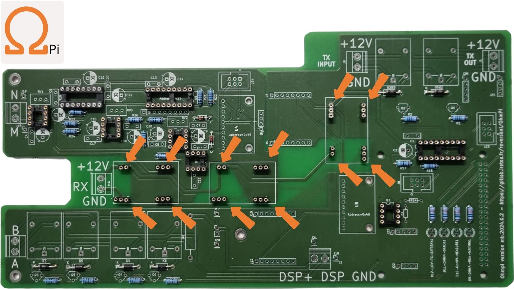
STEP 9: Soldering twelve cut sockets for 3 THD.

STEP 10: Soldering header socket 1 row 10 positions.

STEP 11: Soldering header sockets with 1 row and 8 positions.
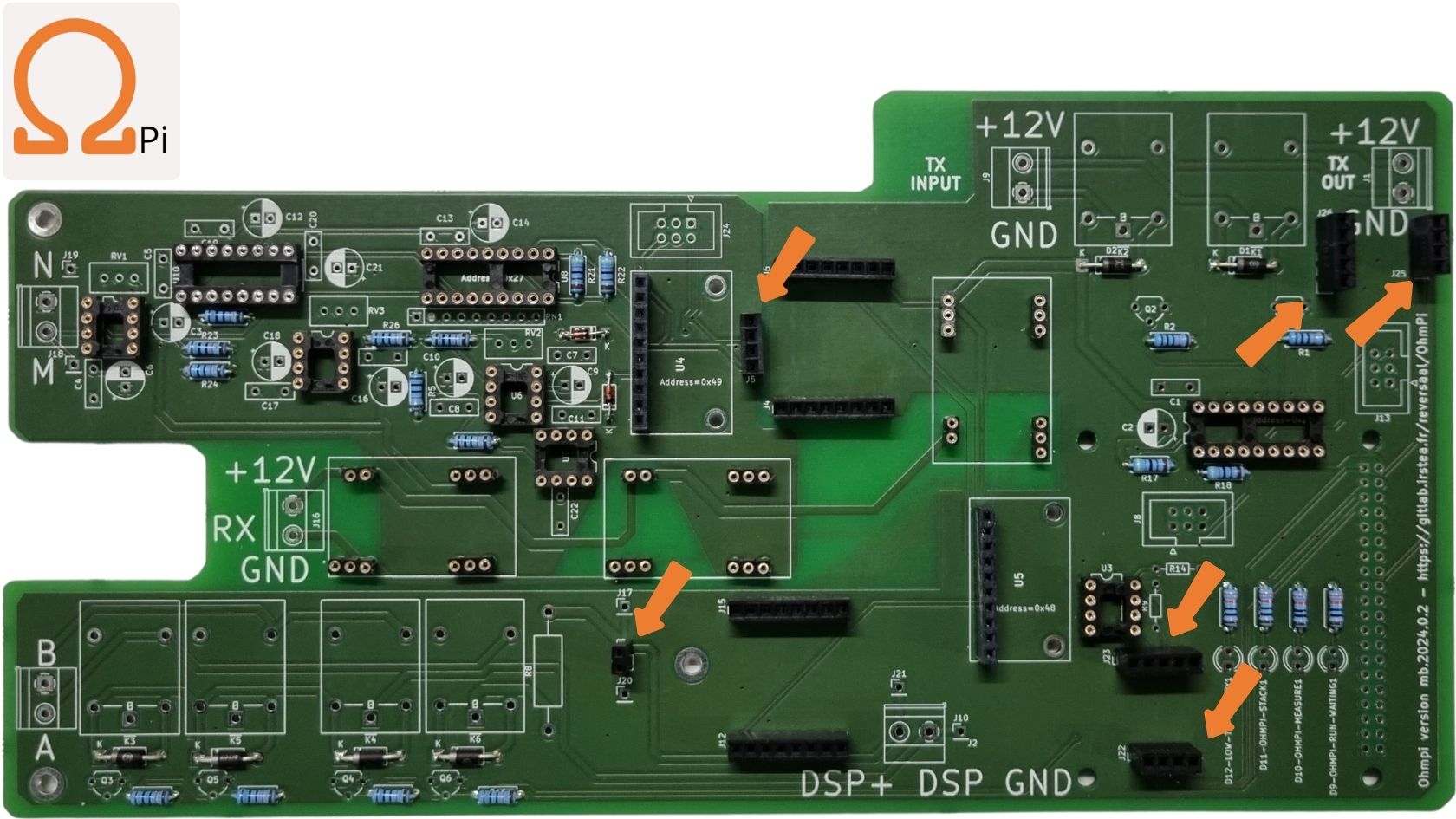
STEP 12: Soldering 1 header (1 row, 2 positions -> cut a bigger one), 3 * 1r4p and 2 * 1r5p.
Information about light-emitting diode

STEP 13: Installation of four light-emitting diodes. Pay attention to the polarity. Short leg side towards the bottom.
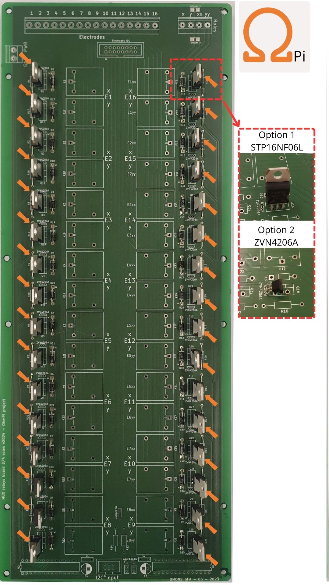
Information about MOSFET Metal Oxide Semiconductor Field Effect Transistor
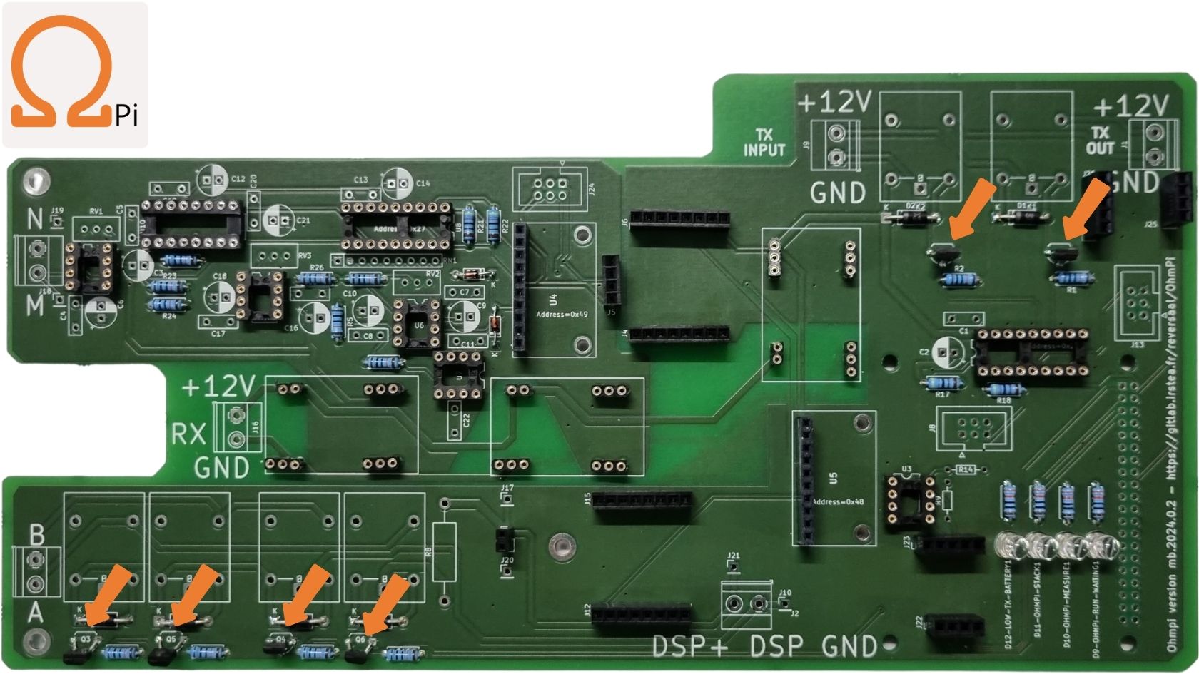
STEP 14: Soldering six MOSFET ZVN4206 or ZVN4306.
What is a CAPACITOR?
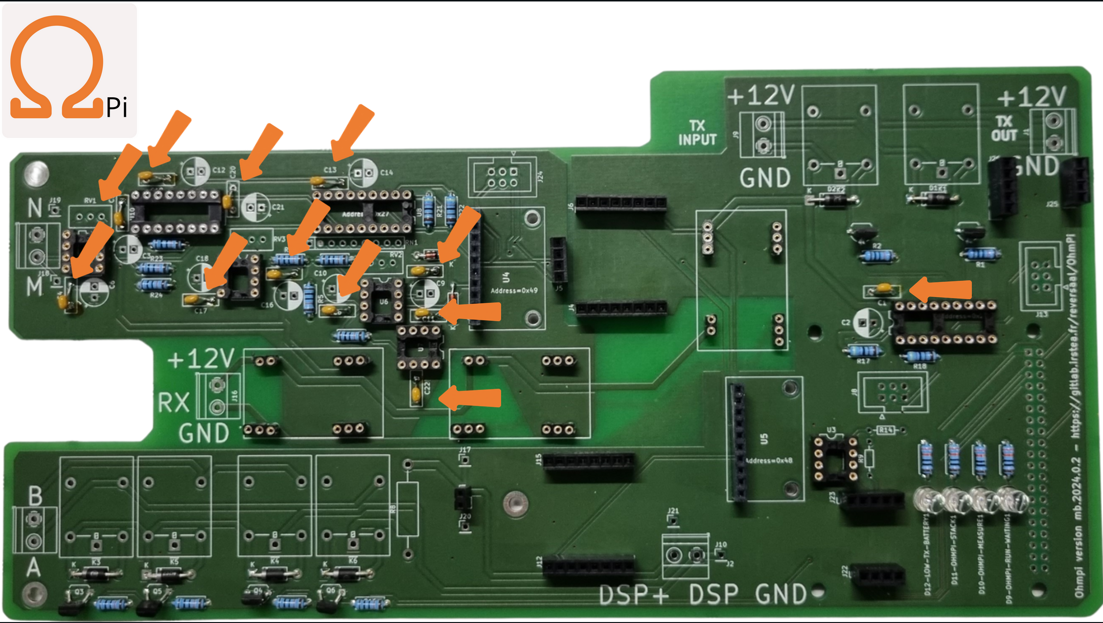
STEP 15: Soldering twelve 100 nF 50V tantalum capacitors. These have no polarity.
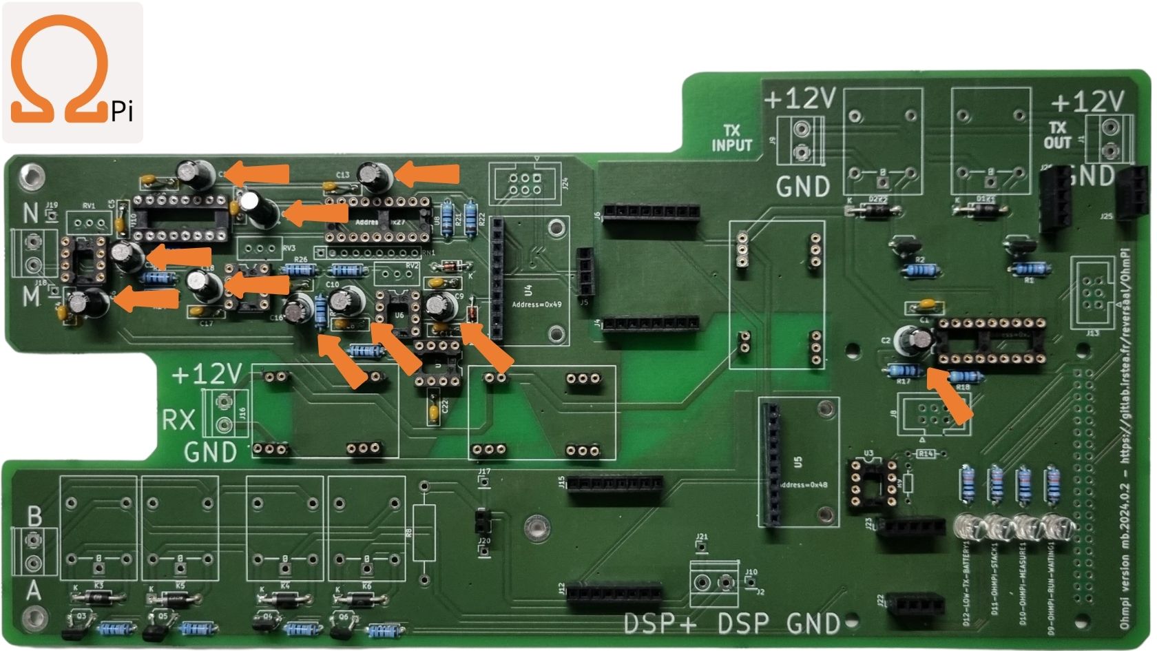
STEP 16: Soldering ten 10 µF 50V Electrolytic capacitors, pay attention to capacitor polarity.
Warning
In this version, we used a shunt resistor of 2 Ohms, which limits the current measurement to 48 mA. If the current is expected higher than this value, you can replace the shunt resistor to a lower resistance value (e.g. for configuration with DPH5005: 1 Ohm for currents up to 100 mA or 0.5 Ohm for currents up to 200 mA). Don’t forget to change the shunt value in the config.py file (value associated to key ‘R_shunt’ in the OHMPI_CONFIG dict).

STEP 17: Soldering the 2 Ohms shunt resistor.

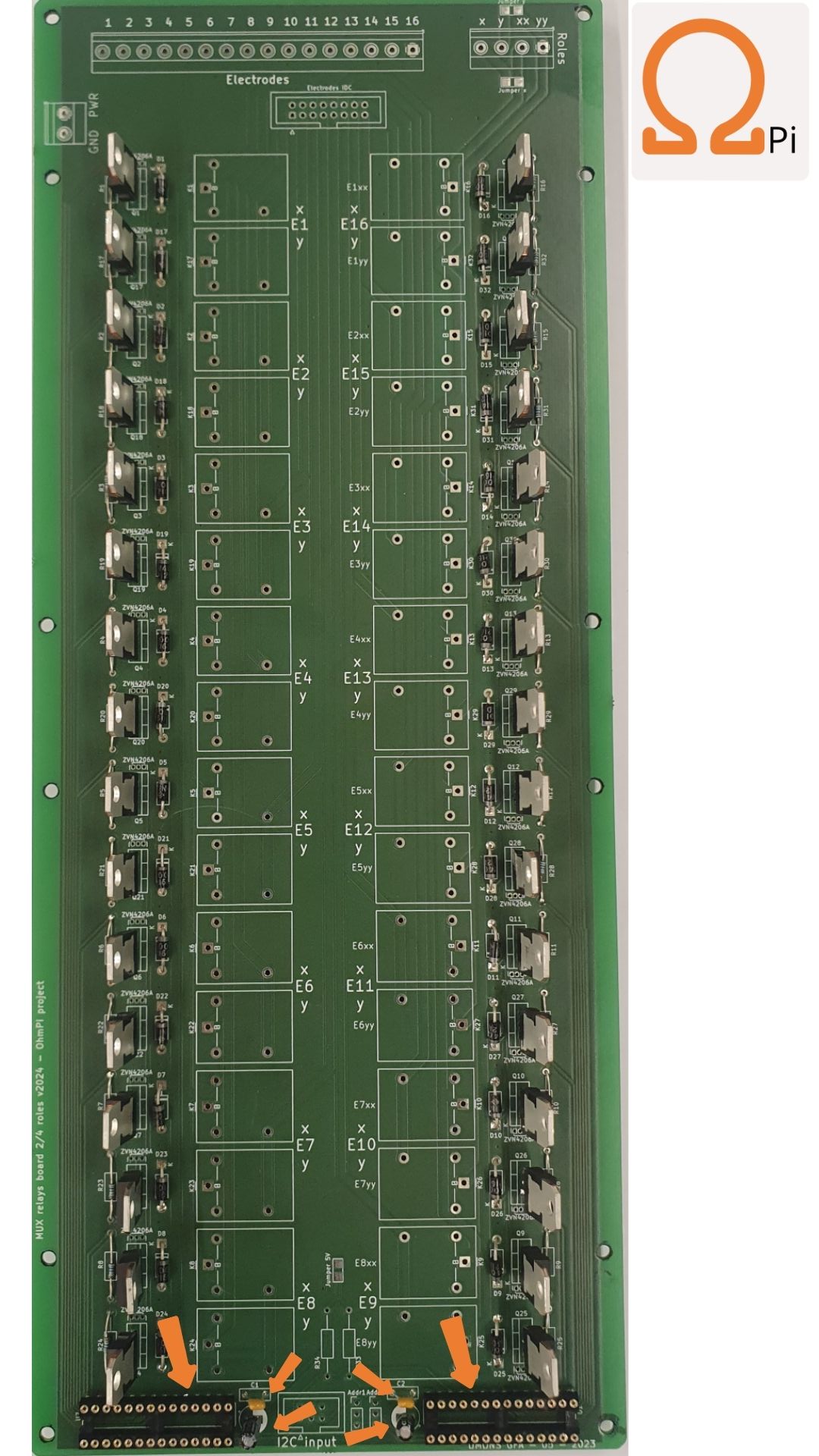
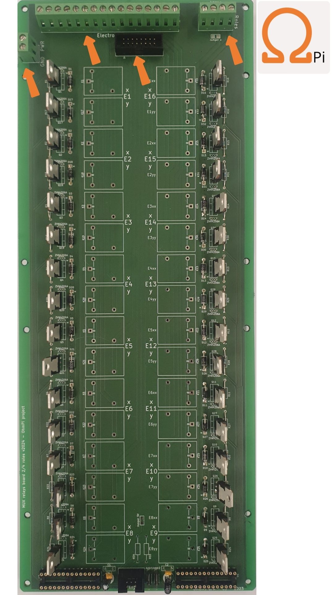
STEP 18: Soldering the three IDC 6 pins connectors. Pay attention to the orientation of the connector!

STEP 19: Soldering six screw terminals for cable connection.
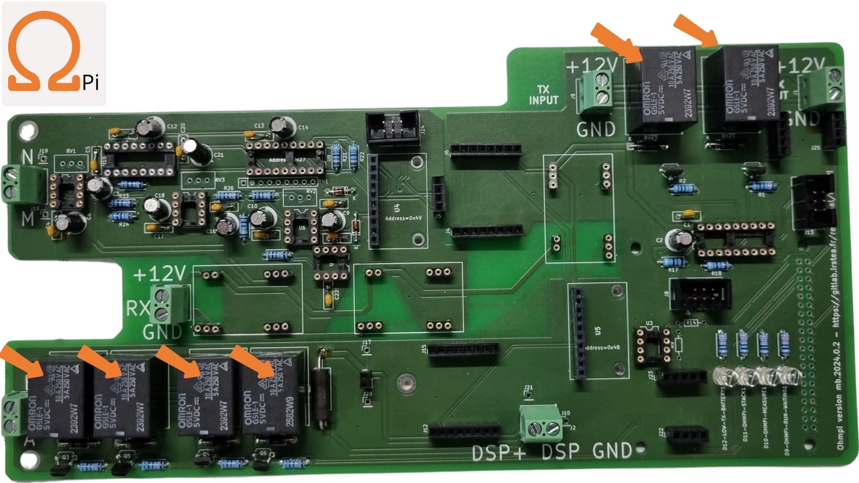
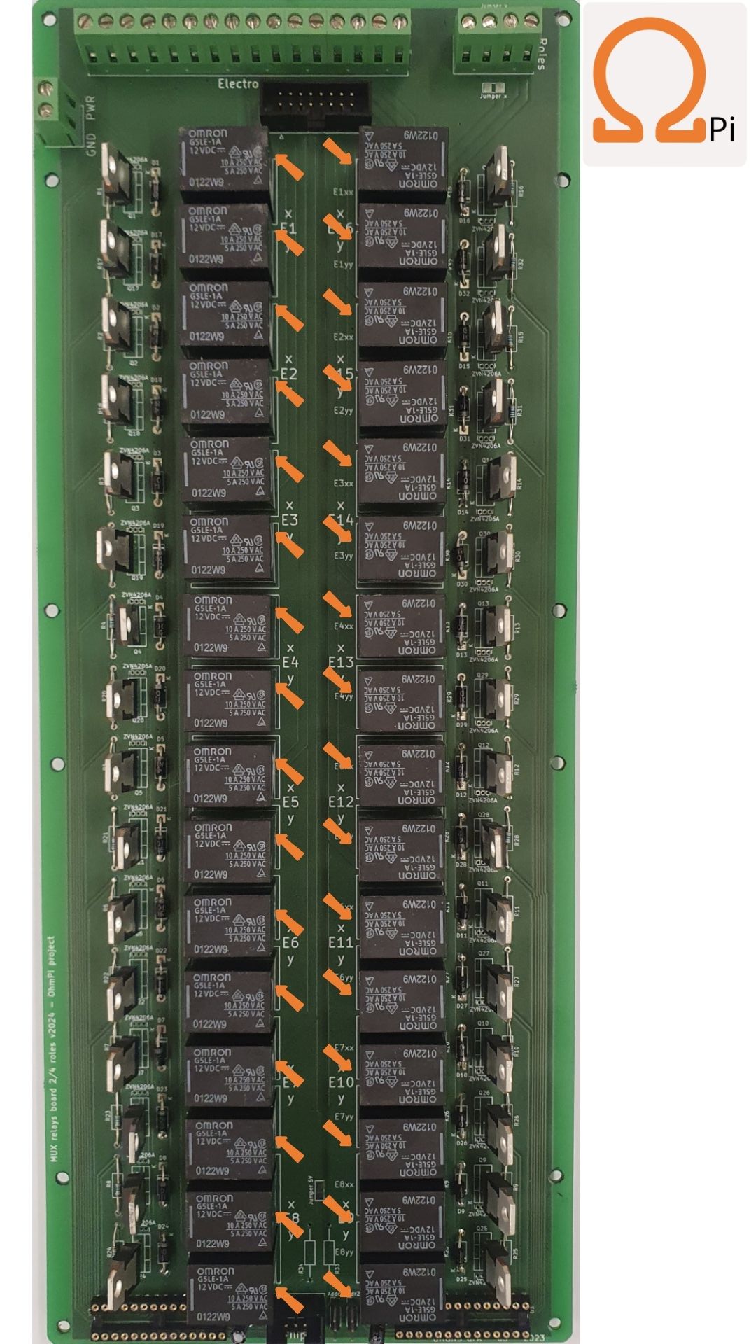
STEP 20: Soldering six Omron G5LE relays 5 VDC. (If your PCB has a discharge relay, mount it too).
Warning
The Raspberry Pi header below need to be soldered on the underside of the PCB.

STEP 21: Soldering the 2x20 header for connection with the raspberry GPIO on the under side of the PCB.
What is a Op-Amp?
In addition, the notch provides a way to visually identify the orientation of the package.
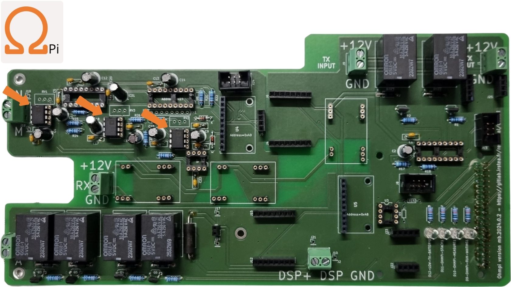
STEP 22: Place the three OP27 on their DIP-8 sockets. The notch must face upwards. Make sure not to confuse OP27 with REF03.
STEP 23: Place the REF03 reference voltage (2.5V) on its DIP-8 socket. The notch must face the right side. Make sure not to confuse REF03 with OP27.
What is an analogue switch?

STEP 24: Place the DG411 (the notch must face the left side).

STEP 25: Place the two MCP23008 on their DIP-16 socket (pay attention to the notches orientation).

STEP 26: Place the three THD, install the right reference at the right place according to the yellow boxes.

STEP 27: Place the ADS1115 board on its female header 1x10 pins.
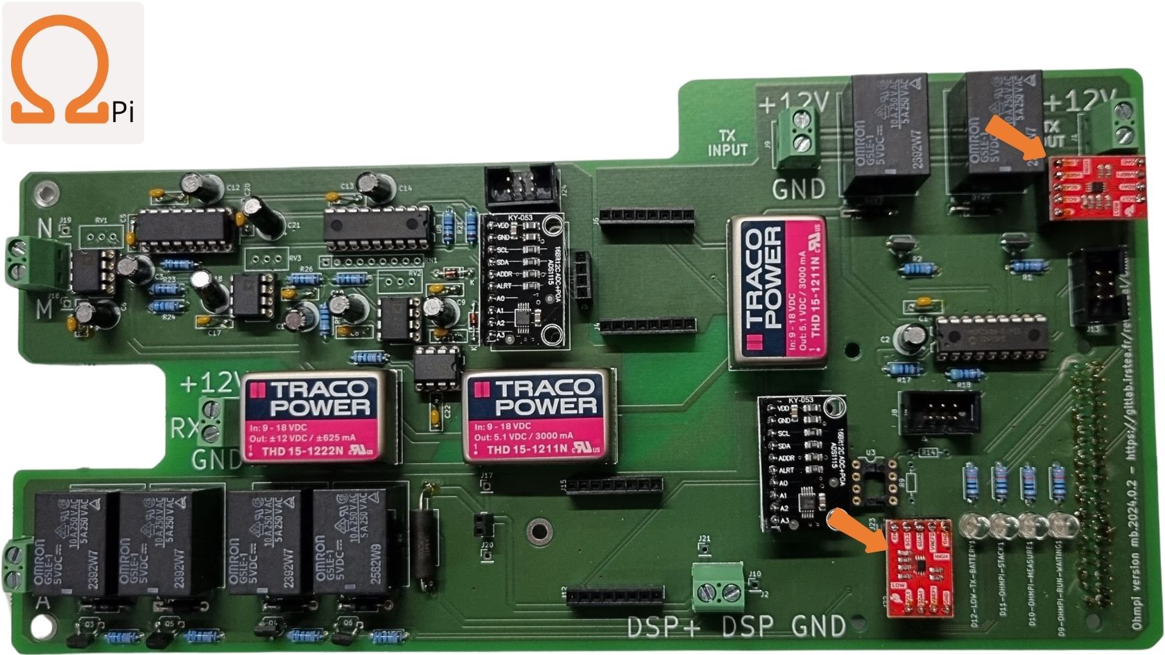
STEP 28: Place the two I2C level adjusters.
STEP 29: Place the I2C isolator add-on board. Make sure you have right selection according to the red box.
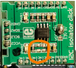
Note
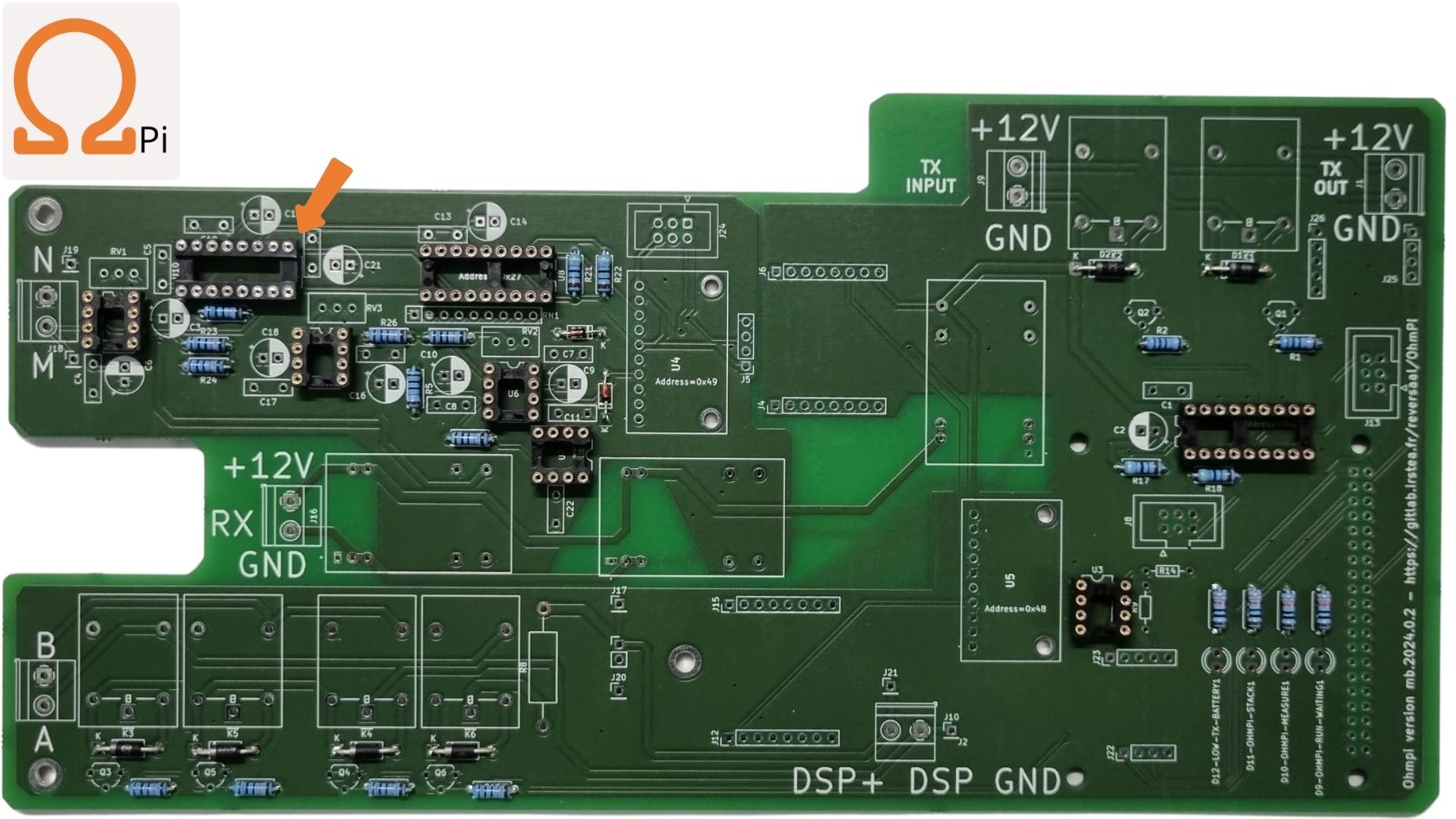
If you have issues with the I2C isolator (e.g. 0x49 and 0x27 are not visible), you may need to remove the pull-up resistor on the I2C isolator as shown above.
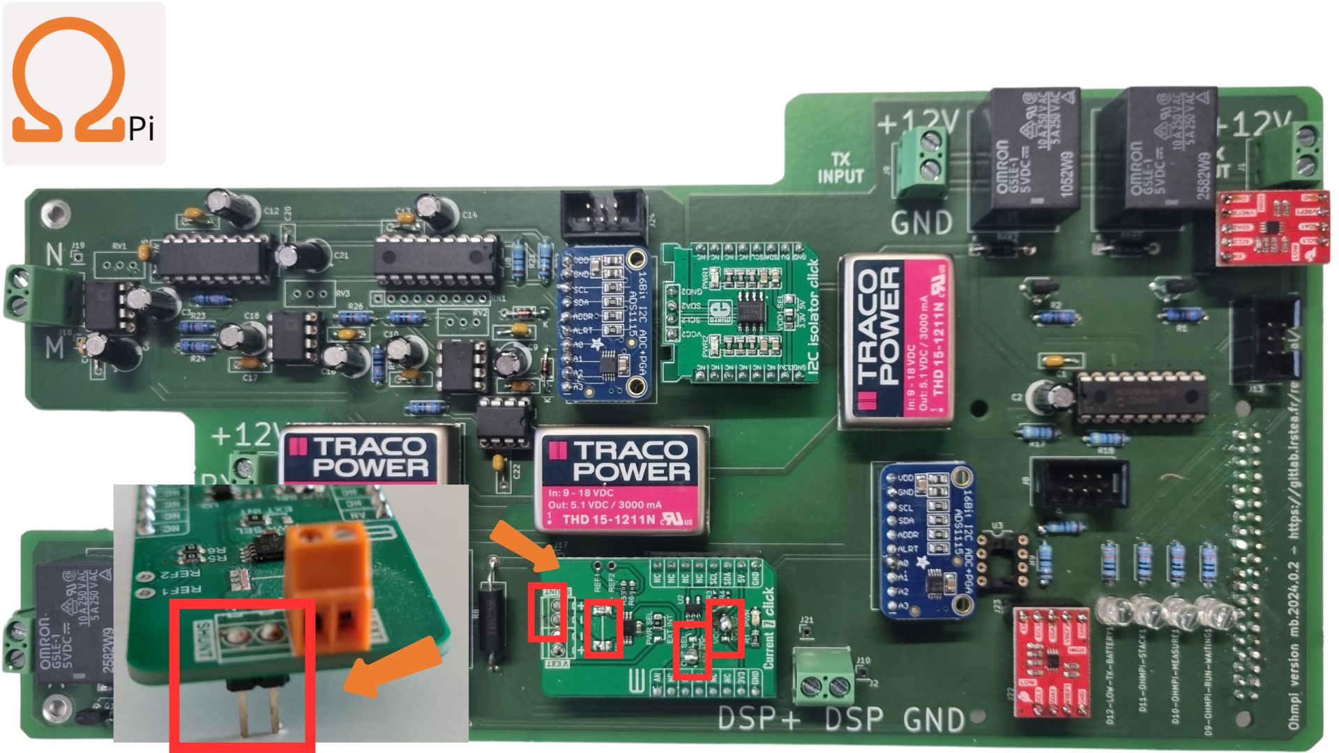
STEP 30: Place the current click add-on board. Make sure you have right selections according to the red boxes.
Note
Don’t forget to add the two header pins below the ‘shunt’ side of the current click so it can be connected to the PCB below.
Checks
Use the picture and table below to manually check with a multimeter for continuity and expected voltage in the measurement board.
Without power off
If a continuity check does not pass it likely means there is an issue with the soldering on the board.

Name |
Power |
Type |
Multimeter BLACK probe |
Multimeter RED probe |
Expected |
|---|---|---|---|---|---|
SC1 |
off |
continuity |
screw terminal Tx in GND |
screw terminal Tx in +12V |
no continuity |
SC2 |
off |
continuity |
screw terminal Tx out GND |
screw terminal Tx out +12V |
no continuity |
SC3 |
off |
continuity |
screw terminal A |
screw terminal B |
no continuity |
SC4 |
off |
continuity |
screw terminal M |
screw terminal N |
no continuity |
SC5 |
off |
continuity |
screw terminal DPS - |
screw terminal DPS + |
no continuity |
SC6 |
off |
continuity |
ADS current 0x48 GND |
ADS current 0x48 VDD |
no continuity |
SC7 |
off |
continuity |
ADS voltage 0x49 GND |
ADS voltage 0x49 VDD |
no continuity |
Warning
Do not power the board if one of the SC (short circuit) tests does not pass!
With power on
To power the board, you need to connect a 12 V source (e.g. battery) on Rx-Batt. If the voltage with I2C (SDA and SCL pins) is not expected, there is likely an issue with pull-up resistors.
Name |
Power |
Type |
Multimeter BLACK probe |
Multimeter RED probe |
Expected |
|---|---|---|---|---|---|
C1 |
off |
continuity |
ADS current 0x48 GND |
Current click GND |
continuity |
C2 |
off |
continuity |
ADS current 0x48 GND |
Raspberry Pi GND |
continuity |
C3 |
off |
continuity |
ADS current 0x48 GND |
MCP23008 Tx 0x21 VSS |
continuity |
C4 |
off |
continuity |
ADS current 0x48 GND |
I2Cext GND |
continuity |
C5 |
off |
continuity |
screw terminal N |
I2C isolator GND2 |
continuity |
C6 |
off |
continuity |
screw terminal N |
ADS voltage 0x49 GND |
continuity |
C7 |
off |
continuity |
screw terminal N |
DG411 GND |
continuity |
C8 |
off |
continuity |
screw terminal N |
MCP23008 MN 0x27 VSS |
continuity |
C9 |
off |
continuity |
ADS voltage 0x49 VDD |
I2C isolator VCC2 |
continuity |
C10 |
off |
continuity |
ADS voltage 0x49 VDD |
MCP23008 MN 0x27 VDD |
continuity |
C11 |
off |
continuity |
ADS voltage 0x49 SDA |
I2C isolator SDA2 |
continuity |
C12 |
off |
continuity |
ADS voltage 0x49 SDA |
MCP23008 MN 0x27 SDA |
continuity |
C13 |
off |
continuity |
ADS voltage 0x49 SCL |
I2C isolator SCL2 |
continuity |
C14 |
off |
continuity |
ADS voltage 0x49 SCL |
MCP23008 MN 0x27 SCL |
continuity |
C15 |
off |
continuity |
ADS current 0x48 SDA |
Current click SDA |
no continuity |
C16 |
off |
continuity |
ADS current 0x48 SDA |
Raspberry Pi SDA1 (p3) |
no continuity |
C17 |
off |
continuity |
ADS current 0x48 SDA |
MCP23008 Tx 0x21 SDA |
continuity |
C18 |
off |
continuity |
ADS current 0x48 SDA |
ADS voltage 0x49 SDA |
no continuity |
C19 |
off |
continuity |
ADS current 0x48 SCL |
Current click SCL |
no continuity |
C20 |
off |
continuity |
ADS current 0x48 SCL |
Raspberry Pi SCL1 (p5) |
no continuity |
C21 |
off |
continuity |
ADS current 0x48 SCL |
MCP23008 Tx 0x21 SCL |
continuity |
C22 |
off |
continuity |
ADS current 0x48 SCL |
ADS voltage 0x49 SCL |
no continuity |
C23 |
off |
continuity |
ADS current 0x48 VDD |
Current click 5V |
continuity |
C24 |
off |
continuity |
ADS current 0x48 VDD |
Raspberry Pi 5V (p2) |
continuity |
C25 |
off |
continuity |
ADS current 0x48 VDD |
MCP23008 Tx 0x21 VDD |
continuity |
C26 |
off |
continuity |
ADS current 0x48 VDD |
I2Cext 5V |
continuity |
V1 |
on |
voltage |
screw terminal Tx in GND |
screw terminal Tx in +12V |
12V |
V2 |
on |
voltage |
screw terminal Rx GND |
screw terminal Rx +12V |
12V |
V3 |
on |
voltage |
ADS current 0x48 GND |
ADS current 0x48 VDD |
5V-5.2V |
V4 |
on |
voltage |
ADS current 0x48 GND |
ADS current 0x48 SDA |
5V-5.2V |
V5 |
on |
voltage |
ADS current 0x48 GND |
ADS current 0x48 SCL |
5V-5.2V |
V6 |
on |
voltage |
ADS current 0x48 GND |
I2Cext SDA |
5V-5.2V |
V7 |
on |
voltage |
ADS current 0x48 GND |
I2Cext SCL |
5V-5.2V |
V8 |
on |
voltage |
screw terminal N |
ADS voltage 0x49 VDD |
5V-5.2V |
V9 |
on |
voltage |
screw terminal N |
ADS voltage 0x49 SDA |
5V-5.2V |
V10 |
on |
voltage |
screw terminal N |
ADS voltage 0x49 SCL |
5V-5.2V |
V11 |
on |
voltage |
screw terminal N |
ADS voltage 0x49 A0 |
2.499V-2.501V |
V12 |
on |
voltage |
Current click GND |
Current click AN |
<5mV |